


- Decide what the prototype needs to represent
- Separate the plenum, runners, and interfaces
- Choose a route that matches quantity and learning goals
- Treat internal passages as geometry, not hidden volume
- Protect the mounting flange and sealing stack
- Match material to the test, not just the eventual vehicle
- Make inspection meaningful for the hidden features
- Give suppliers a useful manifold RFQ package
- Frequently asked questions
Decide what the prototype needs to represent
“Prototype” can describe very different parts. A packaging model may need the correct outer envelope, mounting points, and connector clearances while leaving internal passages unfinished. A functional flow article needs a more faithful internal geometry and a material or surface condition appropriate to the test. An assembly sample may emphasize sealing faces, fasteners, sensor bosses, and throttle-body interfaces. These requirements should not be blended into one vague request for a production-equivalent part. Before selecting a route, list the questions the build must answer and identify the features that affect each answer. If the goal is engine-bay clearance, inaccessible internal detail may not justify its cost. If the part will be used for a defined flow or pressure test, internal transitions and port geometry become central. The drawing should distinguish representative surfaces from simplified ones so downstream teams do not interpret a cosmetic prototype as validated hardware.
Separate the plenum, runners, and interfaces
The geometry often combines a plenum volume, several runners, a mounting flange, throttle or inlet connection, sensor provisions, and local ribs. Each feature creates different manufacturing constraints. Long enclosed runners are difficult to produce as one machined piece; a multi-piece assembly can provide tool access but introduces seams, alignment features, and sealing decisions. A molded or cast route can consolidate geometry but depends on tooling, draft, wall transitions, and production assumptions. Model the interfaces explicitly. Show the engine-side port pattern, gasket boundary, fastener access, connector clocking, and any adjacent components that constrain the housing. Mark which internal features are functional for the planned test. Where two shells or sections join, define locating features and a repeatable assembly reference rather than relying on the outer contour alone. This makes it easier to compare a machined assembly with a later molded or cast design.
Choose a route that matches quantity and learning goals
For a small number of parts, CNC machining can be useful when the passage layout is accessible from multiple directions or can be divided into components. A machined aluminum body may suit a structural or thermal development article, while a polymer prototype may be preferable when the design intends to move toward a molded thermoplastic. Production-intent aluminum parts may use die casting followed by machining of critical interfaces; molded polymer manifolds may require injection tooling and material-specific design checks. None of these routes is universally best.
| Route | Useful when | Key review before commitment |
|---|---|---|
| CNC-machined sections | Geometry is changing and a limited build must verify interfaces | Tool access, joining method, internal transitions, and assembly repeatability |
| Die-cast blank plus machining | The design and volume justify a near-net metal route | Draft, wall transitions, casting allowance, porosity requirements, and datum creation |
| Injection-molded polymer | A polymer design and production-oriented geometry are defined | Resin specification, fiber orientation, shrinkage, gate strategy, and tooling commitment |
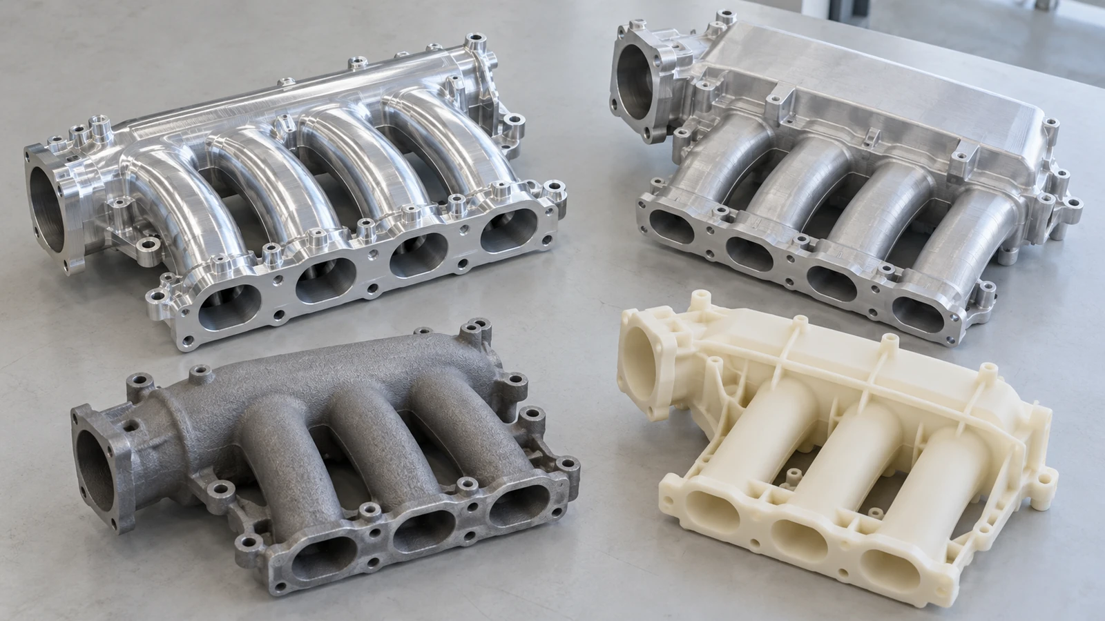
Prototype and production routes can differ, but that difference should be visible in the validation plan. The site’s automotive manufacturing-process overview helps frame route selection; a part-specific DFM review still needs the actual geometry and acceptance criteria.
Treat internal passages as geometry, not hidden volume
Runner cross-sections, bends, transitions, and local steps can affect what a flow test measures. A passage that is easy to machine may not preserve the intended design; a smoother path may need a split construction or a different process. Specify the internal geometry that matters and identify where a seam, plug, or tool-access feature is acceptable. If the model contains small radii or inaccessible corners, confirm what can be produced and inspected rather than assuming a CAD surface is automatically manufacturable.
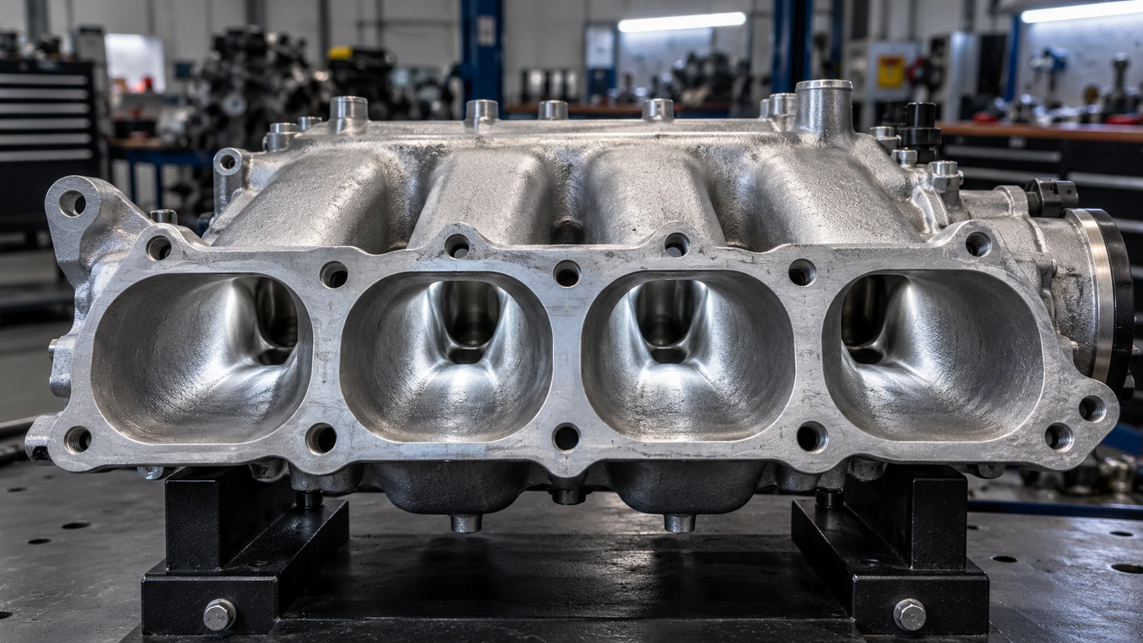
Also define how internal edges are handled. A sharp edge at a port entrance may be intentional, while loose burrs or chips are not. Deburring instructions should protect designed edges and identify passages that require cleaning or visual inspection. If a pressure or leak test is needed, state the ports, fixture arrangement, test medium, condition, and acceptance rule. A leak check does not automatically verify passage dimensions or surface condition.
Protect the mounting flange and sealing stack
The engine-side flange is a functional interface, not merely a flat finishing operation. Its flatness, port-to-hole relationship, surface condition, and gasket boundary may all affect assembly. Thin flange sections can move during stock removal or clamping. Plan support points near the machined face, avoid measuring a part while it is distorted in a fixture, and inspect the released component in the reference condition defined by the drawing. For a multi-piece design, locate the joining faces and fasteners so the assembled ports remain aligned. State whether dimensions apply to individual components or the assembled manifold. If a sealant, gasket, or insert is part of the test assembly, provide that information before quoting; the supplier should not infer the intended stack from a rendering. The automotive low-volume manufacturing guide is relevant when the team is deciding how much assembly and process representation a limited build needs.
Match material to the test, not just the eventual vehicle
Aluminum and engineering thermoplastics bring different stiffness, mass, thermal, chemical, and manufacturing behavior. Within a polymer family, resin grade, reinforcement, moisture condition, and processing history can change dimensional and mechanical behavior. A generic material name is therefore not enough for a test article expected to represent a specific design. Give the supplier the required grade or an approved equivalent process, and state whether the part is for fit review, flow evaluation, or another purpose. When the prototype material differs from the planned production material, document the limitation. A machined aluminum article may confirm package and port relationships but cannot stand in for every property of a molded reinforced polymer part. Likewise, a quick polymer mock-up may show assembly access without representing heat exposure or long-term service. The existing automotive material-selection guide provides general context, while the program specification determines the actual material.
Make inspection meaningful for the hidden features
External dimensions are relatively easy to report; internal passage verification may require a different plan. Depending on the design, teams can consider accessible probe measurements, inspection fixtures, borescope views, sectioned first articles, computed tomography by an agreed provider, or process records. The method should be selected for the feature and acceptance requirement. Do not imply that a single inspection technology can resolve every internal surface or replace a defined drawing tolerance. Prioritize the measurements tied to the stated build purpose: flange flatness and hole pattern for assembly, runner geometry for a flow study, or mounting envelope for package review. Record the datum setup, revision, and whether measurements were made before or after finishing. If the part is assembled from several sections, inspect both critical components and the assembled relationship where the test depends on it.
Give suppliers a useful manifold RFQ package
Include a revision-controlled CAD model and drawing, quantity, material grade and condition, intended build stage, surface requirements, assembly details, critical dimensions, and the inspection report requested. Identify whether the part is a visual mock-up, a fit prototype, or an article for a defined functional test. Mark simplified geometry and ask the supplier to call out tool-access limits, split-line assumptions, sealing interfaces, and any feature that cannot be inspected as drawn. Ask for a route comparison only when you can compare equivalent scope. A machined assembly, a cast blank, and a molded part do not have the same tooling assumptions or validation value. A clear RFQ lets engineering weigh lead time, cost, material representation, and learning value without treating a prototype as a substitute for production validation.
Frequently asked questions
Can a CNC-machined intake manifold represent a molded production part?
It can represent selected geometry or interfaces, but the team should document differences in material, joining method, and production process. It should not be assumed to reproduce every production behavior.
Should an intake manifold prototype include every internal runner detail?
Only when those details matter to the build’s purpose. A packaging model and a flow-test article need different levels of internal fidelity.
What must be specified for a leak test?
Identify the ports and fixture, test medium and conditions, duration where relevant, and the acceptance criterion. The drawing or test plan should define what result is acceptable.