


A robot controller enclosure is not just a box around a circuit board. It must support mounting, protect electrical hardware from the operating environment, provide service access, route cables without sharp interference, and manage heat paths that can change as the system is installed. A design that solves only the outer shape may arrive at assembly with misaligned connector cutouts, inaccessible fasteners, or a cover that cannot be removed without disturbing nearby equipment.
For a manufacturing partner, the right starting point is to identify what the enclosure actually contains and how it is used: a stand-alone cabinet, a compact controller housing mounted on a robot, or a protected electronics module inside a larger machine. The enclosure’s size, loads, service interval, ingress exposure, grounding strategy, and production quantity all affect the process choice. That makes the topic a focused extension of the broader robotics and automation manufacturing scope, not a generic discussion of robot covers.
- Start with the electronics and installation envelope
- Treat heat, shielding, and grounding as interfaces
- Choose fabrication around geometry and volume
- Control the features that make assembly repeatable
- Compare enclosure materials by function
- Prototype the service task, not only the fit
- What belongs in the RFQ package
Start with the electronics and installation envelope
Before choosing a process, map the internal stack: controller boards, power components, connectors, heat-generating parts, cable bends, and mounting points. Then define the external boundaries imposed by robot links, machine guards, operator access, or nearby moving equipment. This exercise often reveals that the enclosure needs a structural frame and a removable cover rather than one deep shell. It can also show that a cable connector needs a different orientation to avoid collision or reduce strain on the harness.
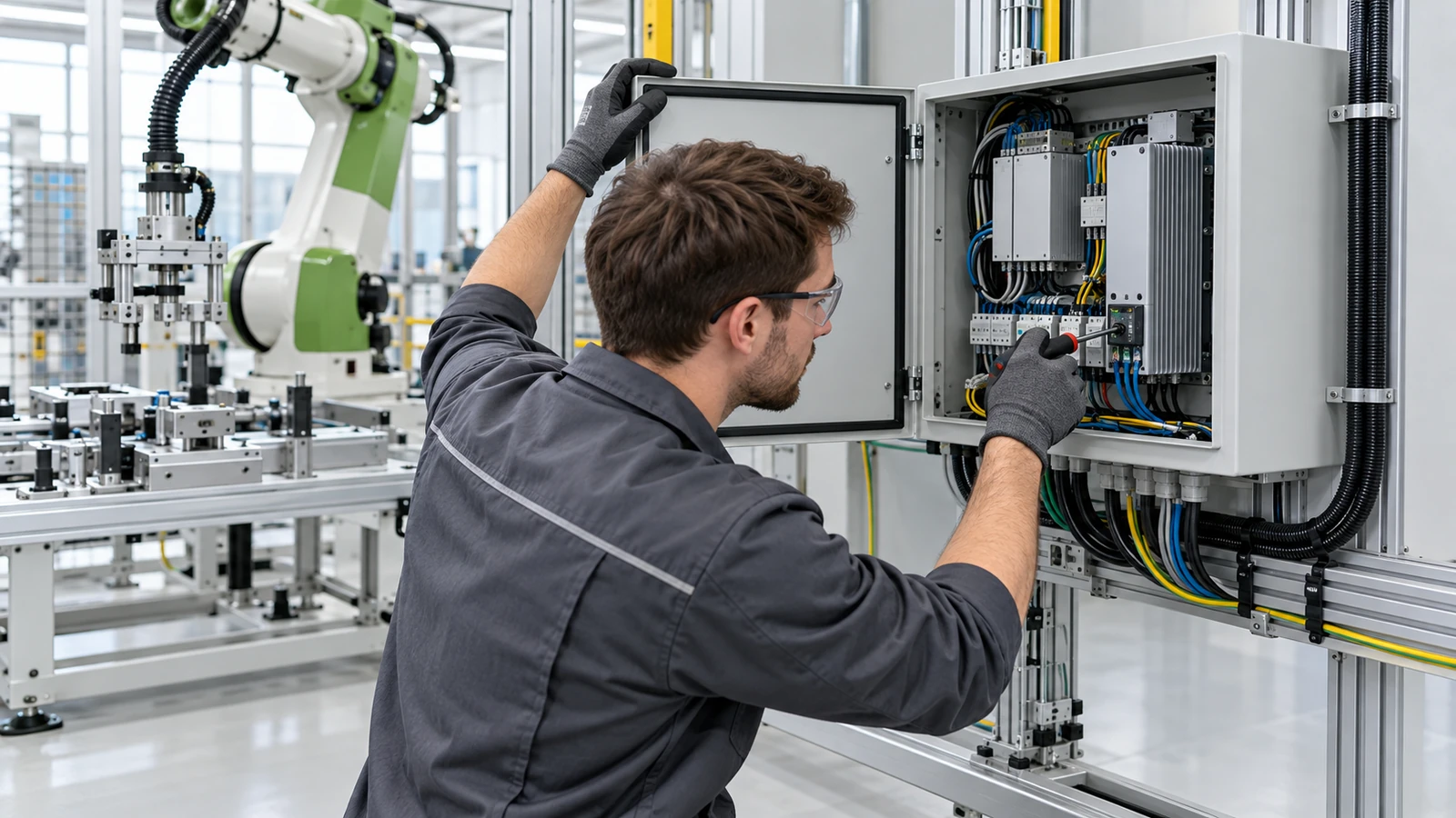
Service access is easy to miss in a shaded CAD model. Ask whether a technician can reach every fastener with a tool, unplug connectors without bending the cable beyond its allowable radius, and remove the cover while the robot is installed. If the electronics require replacement as a module, the mounting scheme should make that module removable without dismantling unrelated mechanical parts. These observations can simplify the design before the first metal is cut.
Separate enclosure requirements from requirements that belong to the electronics or complete robot. The mechanical supplier can manufacture defined walls, flanges, inserts, cutouts, and finish features to drawing, but electrical performance, wiring, software, and system-level compliance depend on the design authority and validation plan. Clear scope prevents a fabricated shell from being mistaken for a fully qualified control system.
Treat heat, shielding, and grounding as interfaces
Controller electronics may reject heat through the enclosure, an internal spreader, a fan path, or a separate thermal interface. The mechanical design needs to show where contact is intended and how flatness, fastener preload, insulation, and surface treatment affect that contact. A painted or anodized surface may be desirable on an exterior wall yet unsuitable at a conductive bonding point unless a deliberate contact feature is specified. Do not assume that every metal-to-metal joint provides the electrical connection the system needs.
Electromagnetic shielding is likewise a system property. A continuous conductive boundary, seams, cable entries, apertures, and gasket compression can all influence the result. The enclosure maker should receive the defined interface requirements and controlled drawing notes, not be asked to infer an attenuation target from the word “shielded.” If the design includes a conductive gasket, indicate its groove or land, compression approach, and keep-out zones so the fabricated features match the validation plan.
Heat and shielding can compete with access and weight. More ribs may increase stiffness and surface area but obstruct connector clearance. A thicker wall can help with rigidity while adding mass. A plastic panel may improve electrical isolation but require a separate conductive shield or grounding architecture. Resolve these decisions in the enclosure concept rather than adding them late as uncoordinated patches.
Choose fabrication around geometry and volume
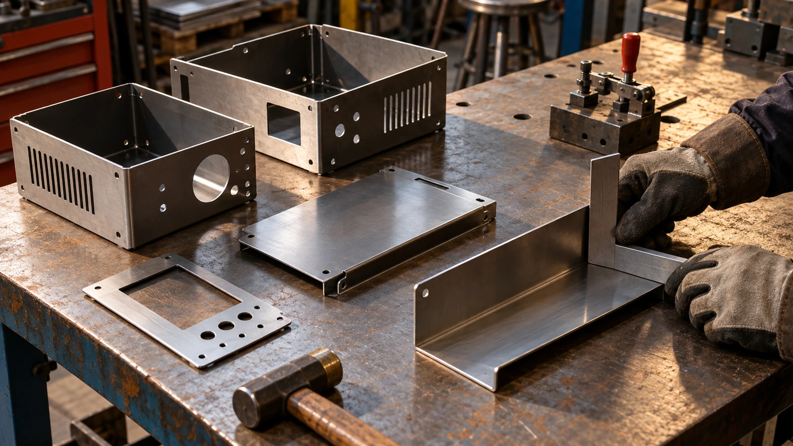
Sheet metal fabrication is often a practical route for cabinets, covers, and brackets made from panels with bends, cutouts, and joined corners. It can support changes between prototype and small batch without committing to a complex mold. Design reviews should account for bend direction, minimum flange geometry, tool access, corner relief, fastener clearance, and the relationship between bend lines and connector openings. A sheet metal fabrication route is relevant when the enclosure is primarily a formed structure.
CNC machining can suit compact housings, heat-transfer features, precise mounting faces, or designs where a one-piece body reduces joints. It can also produce prototypes from solid stock, though material removal and cycle time should be weighed against sheet construction when the design is large or mostly hollow. For a design review, compare the number of parts, sealing seams, access requirements, finishing steps, and expected volume rather than choosing a process by appearance alone.
When a polymer housing is being considered, prototype printing can test cable routing, control layout, and operator access before tooling. For a stable design and appropriate volume, injection molding may become a separate option. These are not interchangeable proof points: a printed shell can help with fit but may not represent molded material behavior, sealing, impact resistance, or production repeatability. The process must match the question the prototype is supposed to answer.
| Route | Can fit when | Review before release |
|---|---|---|
| Sheet metal | The body uses formed panels and accessible joints | Bend access, seams, corner relief, and grounding lands |
| CNC-Bearbeitung | Compact geometry or critical faces dominate | Stock removal, tool access, pockets, and finish allowances |
| Molded polymer | Geometry is stable and volume supports tooling | Draft, wall transitions, inserts, shrinkage, and validation scope |
Control the features that make assembly repeatable
Not every enclosure dimension needs the same tolerance. Prioritize mounting datums, connector cutouts, board supports, cover alignment, gasket lands, and heat-transfer interfaces according to their function. A broad cosmetic panel may accept more variation than a connector pattern that must mate with a harness or a mounting face that locates the controller relative to the robot.
For a multi-panel enclosure, the tolerance stack includes bends, welds, inserts, coatings, and assembly. A hole that is correctly positioned before forming can shift relative to a mating component after the bend sequence. A coating can change a close-fitting edge or grounding point. Identify which dimensions are checked on the formed part, which are checked after finish, and which are verified in the assembled condition.
Fastener strategy also influences repeatability. Captive hardware, threaded inserts, weld nuts, or direct threads each have different service and manufacturing implications. The drawing should state the hardware, location, orientation, and any requirement for repeated removal. If a cover is opened frequently, a design that protects threads and keeps small fasteners captive may improve maintenance without requiring an unnecessarily complex enclosure.
Compare enclosure materials by function
Aluminum can be useful when low mass, thermal spreading, and machined interfaces matter. Steel sheet can be appropriate for a rigid cabinet where formed structure and grounding features are priorities. Stainless steel may be considered when a specific environment calls for its corrosion behavior, while polycarbonate or another engineering plastic can support electrical isolation or transparent inspection windows. The correct selection depends on the controller’s environment and system requirements, not a universal ranking.
State the grade, thickness or stock condition, surface finish, and coating requirements. Include any keep-out or masking details for bonding surfaces, gasket seats, and thermal contacts. Where the enclosure combines metal and plastic, define how inserts are retained and how differential movement or fastener loading is addressed. The site offers CNC aluminum material options und polycarbonate machining information for initial comparison, but the final specification must follow the actual controller design.
Prototype the service task, not only the fit
A useful first article should test more than whether the cover closes. Mount the enclosure in a representative orientation, route real cable samples, install the actual board or a dimensionally accurate surrogate, and perform the intended service operation. If the team needs to validate heat flow, shielding, vibration, ingress protection, or electrical bonding, define those tests separately and use the appropriate instrumentation and system-level setup.
Capture what changed during the build: a connector moved, a cover seam interfered, a fastener was inaccessible, or a bonding point needed masking. Feed those observations back into the drawing revision before a pilot lot. A prototype that only proves the outer dimensions can miss the real user task: installing, connecting, servicing, and returning the robot to operation.
What belongs in the RFQ package
Send a 3D model and controlled drawing with material, finish, quantity, revision, hardware, and inspection notes. Include the layout of internal electronics, the mounting environment, cable entry direction, thermal interfaces, grounding points, gasket details, and areas that must remain unfinished or masked. State whether the request is for a one-off engineering build, a pilot quantity, or repeat production.
Ask the manufacturing partner to review the features that drive risk: bend accessibility, seam placement, flatness at a thermal interface, insert retention, machining access, or service clearance. If electrical integration and qualification are outside the fabrication scope, state that boundary. Clear inputs allow the quote and first-article plan to address the physical enclosure without claiming responsibility for the complete robot control system.
A reliable controller enclosure emerges when the box is designed around the electronics, installation, and maintenance task together. Before releasing the next revision, walk through a real assembly and service sequence with the drawing in hand; that simple review often exposes the manufacturing detail that matters most.

