


A UAV avionics enclosure has to hold more than a board. It has to preserve connector access, support a mounting pattern, protect wiring, and fit around nearby flight hardware without blocking service or cooling paths. The enclosure may be mounted inside a fuselage, on a frame rail, or as a removable electronics module. Each arrangement changes which faces carry load, where cables enter, and how a technician can reach the hardware.
Treating avionics housing as simply a smaller drone body often leads to avoidable rework. The avionics module has its own interfaces, thermal behavior, grounding or shielding needs, and revision lifecycle. This guide focuses on those mechanical decisions and connects them to drawing-based manufacturing options available for drone and UAV components.
- Define the electronics module before the shell
- Keep connectors, cables, and fasteners serviceable
- Separate environmental protection from assumptions
- Plan heat flow and electrical interfaces deliberately
- Choose a process that matches the revision stage
- Use material selection to solve a stated problem
- Make the enclosure verifiable at assembly
- RFQ details for an avionics housing
Define the electronics module before the shell
Begin with the actual board stack, power components, connectors, antennas, sensors, and harness routes. Include the height of components, not only the board outline. A connector that fits in plan view may collide with a cover wall; a cable that exits sideways may need more space than the device itself. Define which parts are included in the housing supply and which belong to the avionics integrator.
Next map the installation envelope. A housing may be constrained by frame tubes, flight-control linkages, battery access, payload mounts, or a removable nose or belly panel. Show the assembly direction and service path in CAD. If the enclosure must slide into rails or be removed without disturbing other equipment, represent that movement in the model rather than relying on a note that says “serviceable.”
A clear datum strategy makes the relationship between the board and airframe predictable. Specify whether the board is located by posts, slots, a carrier plate, or another feature. Then identify how the housing itself references the aircraft structure. That way board alignment is not left to the tolerance stack of a decorative shell, several loose standoffs, and a hand-fit cover.
Keep connectors, cables, and fasteners serviceable
Connector openings should account for the full connector body, latch movement, strain relief, and the direction in which the plug is removed. Check the opening with a representative cable assembly; CAD models often omit overmolded backshells or the hand clearance needed to release a latch. If a connector needs a dust cap or a sealing boot, reserve the space and confirm that it can be installed after the module is mounted.
Cable bends and tie points can be just as important as the cutouts. A sharp edge can abrade insulation, while a tie point placed too close to a connector can transmit strain to the board. Add radii, grommets, clips, or a separate cable guide where justified by the wiring plan. Make sure the guide can be manufactured and inspected, and do not assume that adhesive-backed accessories will remain attached in every operating environment.
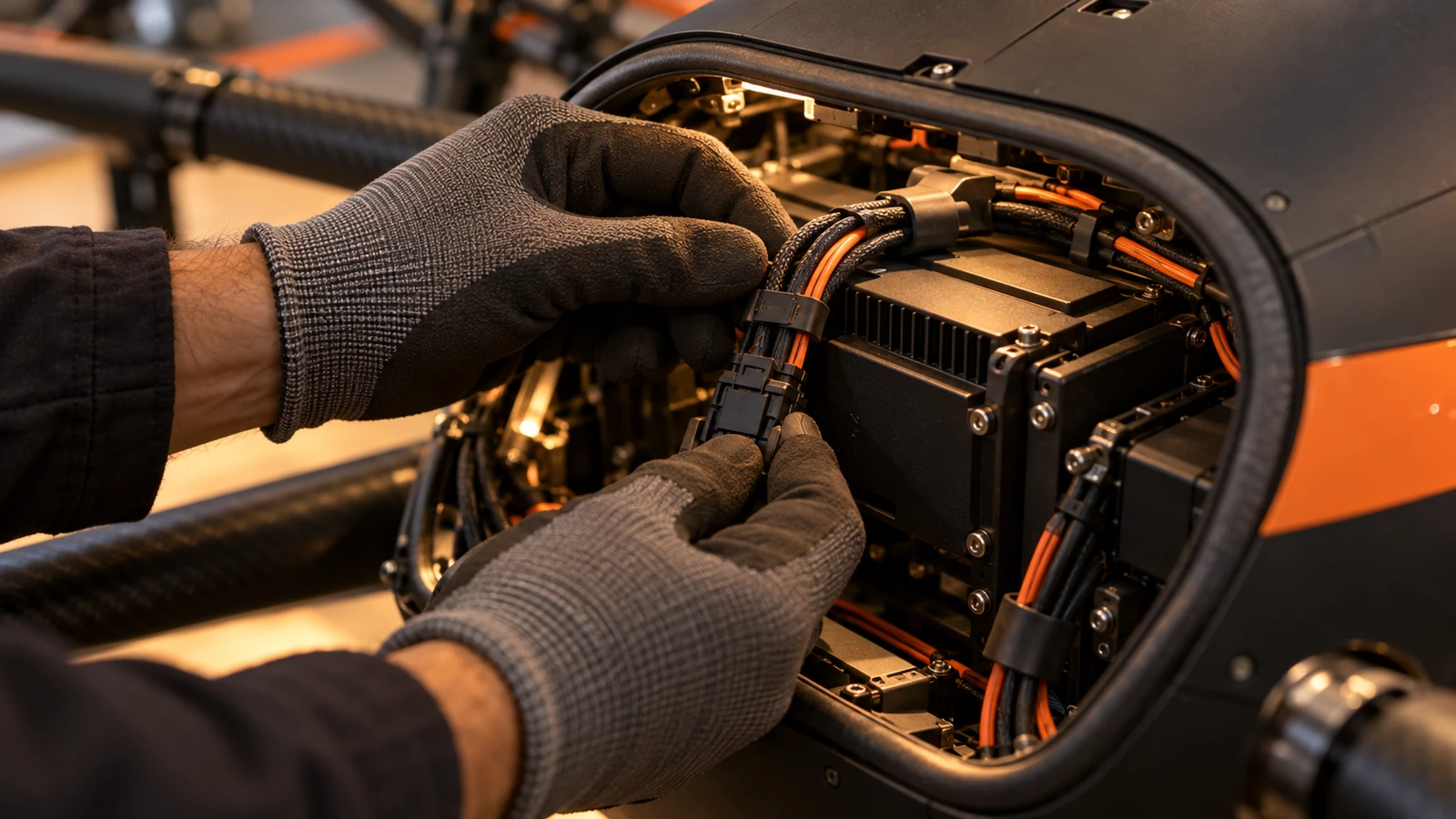
Fastener strategy determines whether the module is practical to maintain. A cover with screws hidden under a wing or payload may technically be removable but not serviceable in the aircraft. Consider captive hardware, insert locations, and the tool approach. For repeated opening, specify the intended fastener and assembly method; the housing design should protect the threads and prevent small hardware from being lost in the airframe.
Separate environmental protection from assumptions
The phrase “protect the avionics” does not define a test requirement. The responsible system team should identify the actual exposure: dust, splash, rain, condensation, cleaning agents, temperature range, vibration, or pressure changes. A labyrinth seam, gasket, vent, or drain may support one objective and undermine another. The housing manufacturer can make the specified geometry, but the complete assembly needs the relevant validation plan.
A gasket is a controlled interface, not a generic strip added at the end. Define the sealing land, groove or compression feature, closure method, and any keep-out for components. Confirm how manufacturing variation, surface finish, coating, and cover stiffness affect compression. If a vent is needed for pressure equalization or heat exchange, its location and protection should be defined with the systems engineer.
Vibration and impact also depend on the mounting architecture. A rigid shell may protect a board from contact while transmitting vibration through the mounting posts. Isolators can reduce transmission but introduce motion and alignment changes. The appropriate solution depends on the electronics and aircraft-level test requirements; the enclosure drawing should not promise protection beyond what the assembled system has demonstrated.
Plan heat flow and electrical interfaces deliberately
If a processor, radio, or power component transfers heat through the housing, specify the intended contact face and thermal interface material. Flatness, clamp load, surface treatment, and assembly sequence can all affect contact. If heat is instead rejected by airflow, make sure the inlet and outlet paths are not blocked by the airframe or adjacent wiring. A housing that is thermally adequate on a workbench may behave differently after installation.
Conductive coatings and anodizing can change electrical continuity at joints. If the enclosure is part of a grounding or shielding path, identify contact lands and areas that must remain uncoated or be masked. If electrical isolation is required, specify insulating features and their mechanical retention. The target belongs to the electrical design and should be checked with the assembled module, not inferred from a material name.
Keep thermal and electrical requirements distinct in the drawing. A single note such as “conductive, heat-dissipating aluminum housing” does not tell a supplier which face contacts a component, where the ground path terminates, or what coating is acceptable. Explicit interfaces make the manufacturing and inspection plan more useful.
Choose a process that matches the revision stage
CNC machining can be appropriate when the design needs precise mounting faces, threaded features, connector cutouts, or integrated heat-transfer surfaces. Sheet metal can suit a larger enclosure assembled from formed panels and brackets. Additive manufacturing can make a fast fit model or a low-volume polymer housing with complex internal supports. The route should follow part size, geometry, material behavior, required evidence, and build quantity.
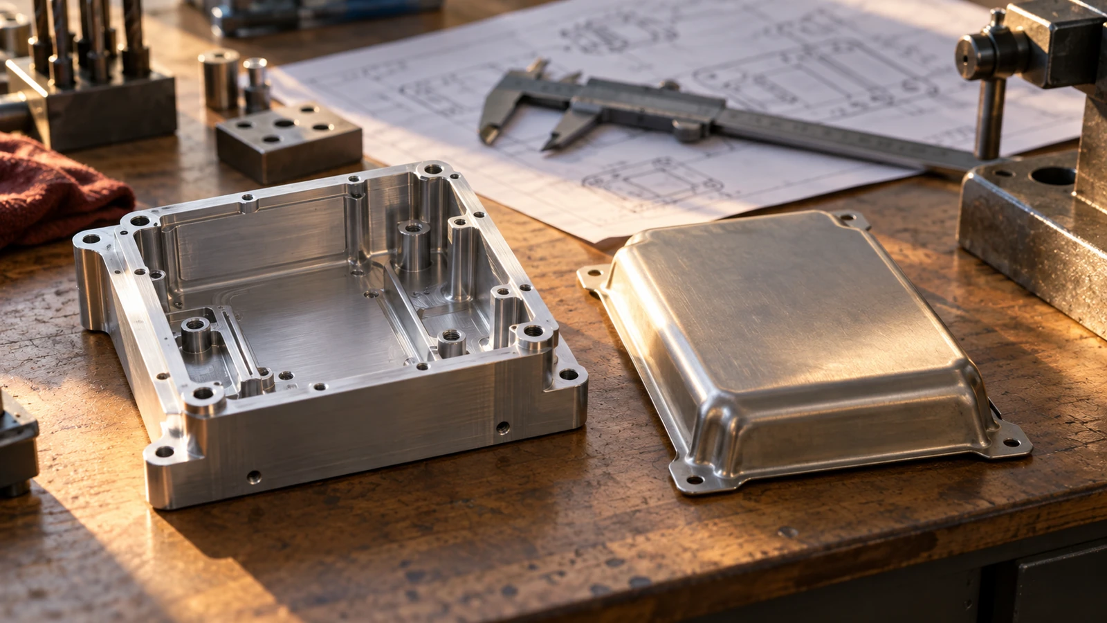
The site provides custom sheet metal fabrication und 3D-Druckdienstleistungen that can support different stages of enclosure development. These options answer different questions. A printed article can validate packaging and service access; it does not automatically prove final environmental performance. A machined metal build can evaluate mounting and thermal interfaces but may not represent the weight or damping of a molded polymer version.
When a design uses multiple pieces, plan joining, fastener access, and inspection after assembly. Weld distortion, formed-panel stack-up, adhesive cure, or insert installation can influence final geometry. When possible, identify the functional assembled dimensions and check them with the mating board or an inspection fixture.
Use material selection to solve a stated problem
Aluminum may be useful when low mass and heat spreading are important and the mounting design benefits from machined features. Engineering plastics can provide electrical isolation, integrated clips, or complex routing features, but grade, process, temperature, moisture, and load duration matter. PEI or another high-performance polymer may be considered for a specific thermal or mechanical requirement, but a material’s name alone is not evidence of flight suitability.
A clear material callout includes grade, condition, color if relevant, finish, and any requirements for outgassing, flammability, or environmental exposure. Those requirements must come from the program, not a generalized marketing claim. Jucheng’s PEI machining information can be used to discuss an option; the engineer responsible for the aircraft must confirm whether it is appropriate for the intended operating envelope.
For mixed-material assemblies, consider galvanic contact, differential expansion, insert pullout, and service life. A metal bracket combined with a polymer cover may ease integration, but the fastener preload and joint movement still need review. A prototype should test the interfaces that matter rather than merely showing that the two components can be assembled once.
Make the enclosure verifiable at assembly
Inspection features should be tied to the board and airframe datums. Relevant checks may include mounting-hole locations, connector cutout positions, cover clearance, gasket lands, and the flatness or position of a thermal interface. The drawing should clarify whether dimensions apply before or after coating and whether the measurement is made on the component or assembled module.
A first-article review should include an assembly sequence with representative hardware. Check that the board installs without bending, connectors can be reached, cables route without pinching, and the cover can be opened as intended. If a particular test is required, identify its method, configuration, and acceptance authority. A dimensional report does not by itself establish ingress, vibration, thermal, or flight performance.
RFQ details for an avionics housing
Provide a controlled 3D model and drawing, board outline and component heights, connector models, cable exits, airframe mounting geometry, hardware, material, finish, quantity, and revision. Include the service sequence and environmental requirements. Mark the critical interfaces and identify features that may still change, so a prototype quote is not mistaken for a production release.
Ask for a DFM review of tool access, thin sections, seam placement, gasket compression, coating masks, insert retention, and inspection setup. Keep electrical integration and system qualification responsibilities explicit. A well-prepared RFQ allows the supplier to review the mechanical housing while the aircraft team retains ownership of system-level requirements.
A useful UAV avionics enclosure makes installation, electrical integration, service, and manufacturing agree with one another. The clearest path is to provide the surrounding aircraft geometry and a real assembly task along with the drawing, then use the prototype to expose the interfaces that a standalone shell model cannot show.

