


A differential housing is judged by relationships hidden inside a compact casting: bearing bores must stay aligned, mounting faces must meet the axle assembly, and machined features must remain tied to the correct datums. That is why automotive differential housing machining is rarely just a sequence of turning and drilling operations. The process plan has to preserve how the housing locates the gears and bearings after it leaves the fixture.
For buyers and design engineers, the most useful early review is a feature map. It identifies which dimensions govern the assembly, how the raw blank will be held, and what evidence will show that the finished geometry is usable. This article focuses on that handoff, particularly for prototypes, variants, and low-volume builds where production assumptions may not yet be fixed.
- Map the interfaces before choosing operations
- Build the datum plan around the assembled part
- Treat the casting as a variable starting point
- Choose a sequence that controls setup transfer
- Inspect the relationships, not only the individual sizes
- Prepare a drawing package that can be quoted
- Five checks before releasing a differential housing build
Map the interfaces before choosing operations
Start by separating the housing’s functional interfaces. Depending on the design, these may include bearing seats, gear or axle bores, a ring-gear mounting face, cover flange, fastener pattern, sealing surfaces, and attachment points. Not every housing uses the same architecture, so the drawing and assembly model must define the actual features rather than relying on a generic part description.
Make a simple relationship map: which features locate the housing, which carry a bearing or gear, which join another component, and which are only clearance or exterior geometry. A bore diameter can be in tolerance while its position relative to another bore is wrong. A flange can be flat while its angle to the bearing axis is wrong. These are assembly-level failures, so the supplier needs to see the relationships that matter.
A useful review asks what happens if each interface moves. Would it affect gear alignment, bearing seating, a seal, a cover, or only a noncritical gap? This question helps avoid two opposite problems: leaving a critical relationship uncontrolled, or applying tight requirements everywhere without a functional reason. The results should appear in the drawing’s datums and geometric controls, not only in a verbal note.
Build the datum plan around the assembled part
Datum selection should reflect how the housing is located in the real assembly and how its critical geometry is measured. A broad machined mounting face may provide a stable reference, but it may not be the primary assembly locator. If the part is centered by a bore or registered by a pilot diameter, that feature may need to lead the datum scheme. The drawing should make the intended setup and inspection references understandable to both manufacturing and quality teams.
Consider how the housing will be clamped. A thin wall, open cavity, or irregular cast surface can deflect under fixture force. That movement may disappear after release, leaving a free-state condition different from the in-process reading. The process plan should support the casting at appropriate areas and avoid using a fragile wall as the only reaction surface when another stable feature is available.
For parts with several related bores, the review should identify whether one setup can establish the critical axes or whether the design requires a controlled transfer between setups. When a transfer is needed, the locating method and recheck point should be documented. A new setup is not automatically a defect, but an unplanned change in reference can make otherwise accurate features inconsistent as a group.
Treat the casting as a variable starting point
Cast housings arrive with variation in stock, draft, surface condition, and local material distribution. The machining allowance must be adequate for the features that need to clean up, while the part must still retain the wall and boss geometry intended by design. If a critical face is too close to the casting surface, some blanks may not provide enough material for a consistent finish cut.
That is a drawing and sourcing issue as much as a machining issue. Identify which surfaces are as-cast and which must be machined. Specify the intended blank, material condition, and revision when those choices affect the process. If the supplier receives only a finished solid model without stock assumptions, they may need to estimate the allowance or ask for clarification before quoting.
Prototypes can help reveal where the blank design or allowance should change, but one sample does not represent a full casting distribution. Record whether the part came from a production-representative source, a one-off blank, or another route. The distinction matters when interpreting cleanup, distortion, or machining effort. A prototype should answer a defined design question rather than imply capability across every future lot.
Choose a sequence that controls setup transfer
A practical sequence typically establishes stable references, machines the interfaces that depend on them, and leaves enough support for finishing operations. The exact order depends on the housing and blank. A team may first create reference pads, then machine mounting faces and bores, and finally complete holes or secondary features. The goal is not to prescribe a universal operation list; it is to avoid machining a critical feature from a reference that will later be removed or changed.
Where the design has a main bearing axis and a perpendicular mounting face, identify which relationship is most important to assembly and how it will be held through the operation plan. A custom fixture may be appropriate for repeat work, while a prototype may use a more flexible setup. In either case, the drawing should define the required result, and the process review should state how the chosen setup maintains it.
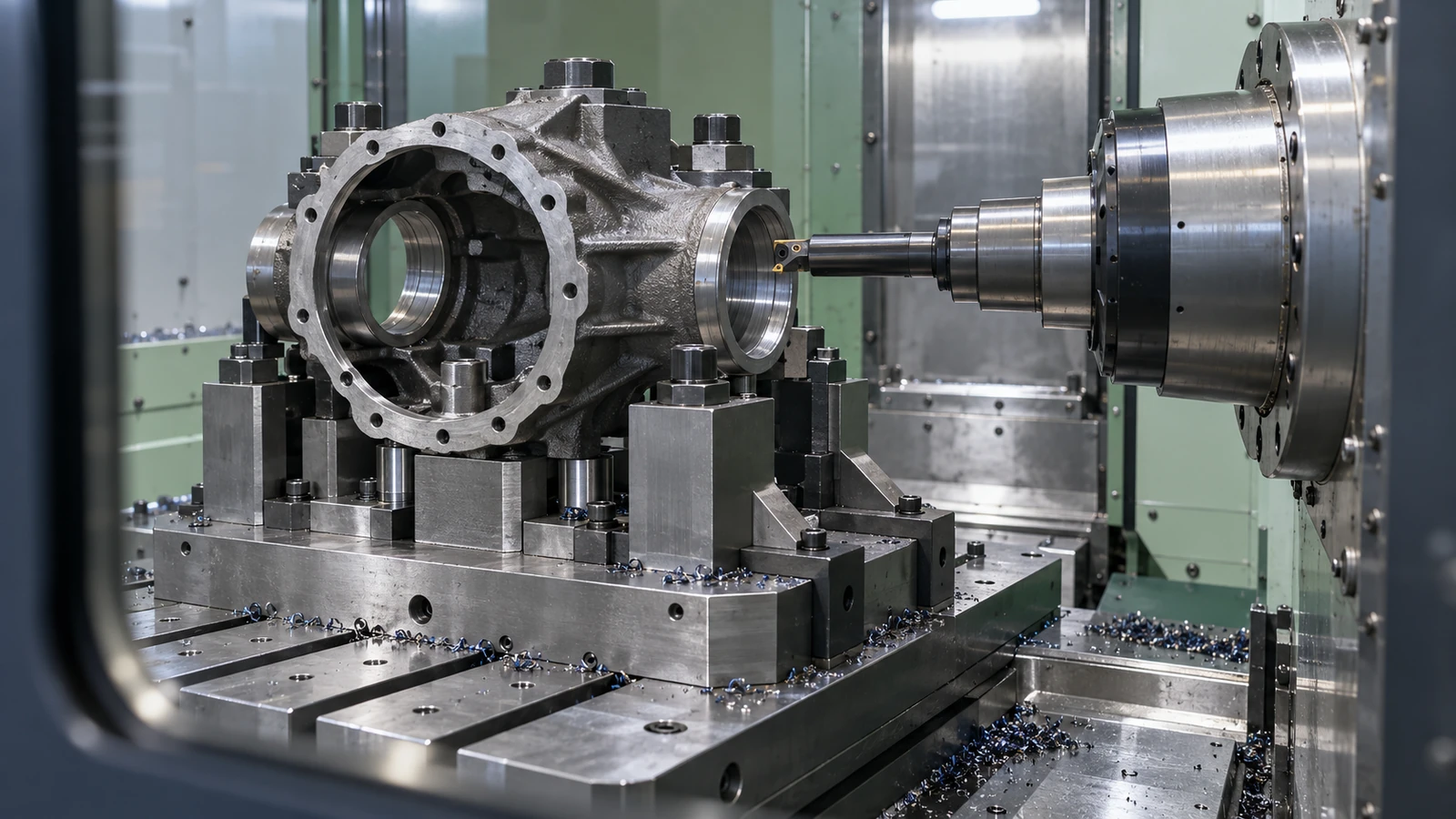
Variation between left- and right-hand housings or different gear ratios can also affect setup planning. Shared fixtures may reduce changeover work, but the locating scheme must still prevent the wrong variant from being machined or inspected against the wrong revision. Clear part identification and a controlled setup sheet are especially valuable when multiple similar castings are on the floor at once.
The broader guide to automotive parts suited to CNC machining can help teams decide which features justify machining for a sample or low-volume build. For a differential housing, the focus should remain on the interfaces that define the assembly rather than on the raw count of machined features.
Inspect the relationships, not only the individual sizes
Inspection planning should follow the feature map. Bore size, center distance, coaxial relationship, face orientation, hole location, and sealing surface condition may each need different measurement methods. The drawing should identify the controlled characteristic and its datum reference so the inspection report answers the engineering question.
A coordinate measurement report can document position and orientation, while gauges or dedicated checks may be suitable for repeated features if their design matches the drawing. The method should be selected based on the feature, tolerance, access, and required record. Do not assume that one measurement system can reach every internal surface or that a single number proves the full assembly condition.

If the housing is inspected while clamped, specify whether the requirement applies in that condition or after release. If finishing, deburring, cleaning, or coating follows machining, decide which checks must occur after those operations. The final condition is what matters to the assembly, so a pre-finish measurement alone may not close the acceptance question.
For a first build, prioritize evidence on a small set of critical relationships and compare it with the CAD and drawing revision used for manufacture. Keep deviations tied to specific characteristics. “Bore alignment issue” is more actionable when the report identifies the two features, reference system, measurement condition, and direction of the observed difference.
Prepare a drawing package that can be quoted
Send a clear 3D model and drawing with the revision, quantity, blank condition, material requirement, machined surfaces, finish, and inspection expectations. Include an assembly view or mating-part data when it clarifies which faces and axes control fit. State whether the request is for a prototype, engineering sample, or repeat lot because the fixture and documentation approach may differ.
Before release, review the model for inaccessible corners, small tools, deep cavities, thin unsupported walls, and features hidden behind the casting. If a critical surface cannot be measured directly, discuss how it will be verified. The design team can often improve access or add a datum feature before the first part is cut.
A supplier review should return questions, not just a price, when the functional relationships are unclear. Clarifying the blank, datum scheme, inspection condition, and revision early can prevent avoidable changes later. For automotive programs that use more than one process, the site’s automotive CNC machining overview provides a broader context for coordinating prototype and production routes.
Five checks before releasing a differential housing build
Before approving the next operation or sample, confirm that the drawing, blank, setup, and evidence refer to one controlled configuration. A short release review can catch gaps that a long inspection report will not fix after the part is machined.
- Part identity: confirm housing variant, handedness if applicable, revision, and the exact model that governs the job.
- Blank condition: record material and stock assumptions, including which faces are supplied as-cast and which must clean up.
- Datums: confirm how the part is located for machining and how inspection recreates the drawing reference frame.
- Critical relationships: name the bores, faces, and mounting features that must be evaluated together, not only as separate dimensions.
- Final condition: identify whether inspection follows deburring, cleaning, coating, or another secondary step and whether the part is free or supported.
Use this review to surface unresolved questions, not to replace the design authority’s requirements. If the sample is intended only for packaging or clearance, state that scope. If it will inform a production decision, identify what additional evidence is still needed. Reliable automotive differential housing machining begins with that shared understanding and ends with measurements tied to the same drawing revision and assembly intent.

