


Two parts called a turbocharger housing may ask very different things from a machine shop. A compressor cover may be designed around an air path, a backplate, and a close-fitting wheel envelope. A turbine housing faces exhaust heat and often begins as a hard-to-cut casting. Treating both as generic housings can hide the real risks: thin walls, interrupted cuts, sealing faces, and geometry that must remain concentric after multiple operations.
Automotive turbocharger housing machining therefore starts with the component’s role and material form. The machining plan should preserve the functional interfaces while acknowledging what the blank and design can support. For a prototype or a changing program, that distinction helps buyers specify the right component and prevents a quote from assuming that a compressor cover and turbine housing are interchangeable.
- First identify which housing is being made
- Let the flow path and wheel envelope guide the model review
- Account for the blank before planning the cut
- Support thin sections without distorting the part
- Plan inspection around concentric and sealing features
- What a useful RFQ should include
- Choose the next build from the evidence you need
First identify which housing is being made
The phrase “turbocharger housing” may refer to the compressor cover, turbine housing, bearing housing, or another related casing. These parts connect to different mating components and may use different blank materials and production routes. A supplier needs the exact part name, drawing, material requirement, quantity, and revision before deciding whether CNC machining, casting, finishing, or a combination is relevant.
| Area to review | Compressor-side example | Turbine-side example |
|---|---|---|
| Main concern | Air-path geometry and wheel clearance | Hot-gas path and heat-resistant blank |
| Interfaces | Inlet, outlet, backplate, mounting features | Manifold, outlet, center housing, fasteners |
| Process question | Can the blank preserve the required wall and contour? | Can the process machine the alloy and verify the required faces? |
This comparison is a planning aid, not a material or design specification. The actual drawing controls. A program may also use different architectures, so confirm which wheel, bearing, or manifold interfaces are included in the supplied part. Avoid sending a combined assembly model without identifying the exact component being quoted.
Let the flow path and wheel envelope guide the model review
Internal contours can leave limited access for cutters and inspection probes. Review the model for narrow passages, recessed surfaces, intersecting ports, and transitions between a volute and adjacent machined faces. The manufacturing team should know which surfaces define the flow path and which are only clearance or cast geometry. If a surface is not intended to be finish-machined, identify its condition rather than leaving the supplier to infer it from the model.
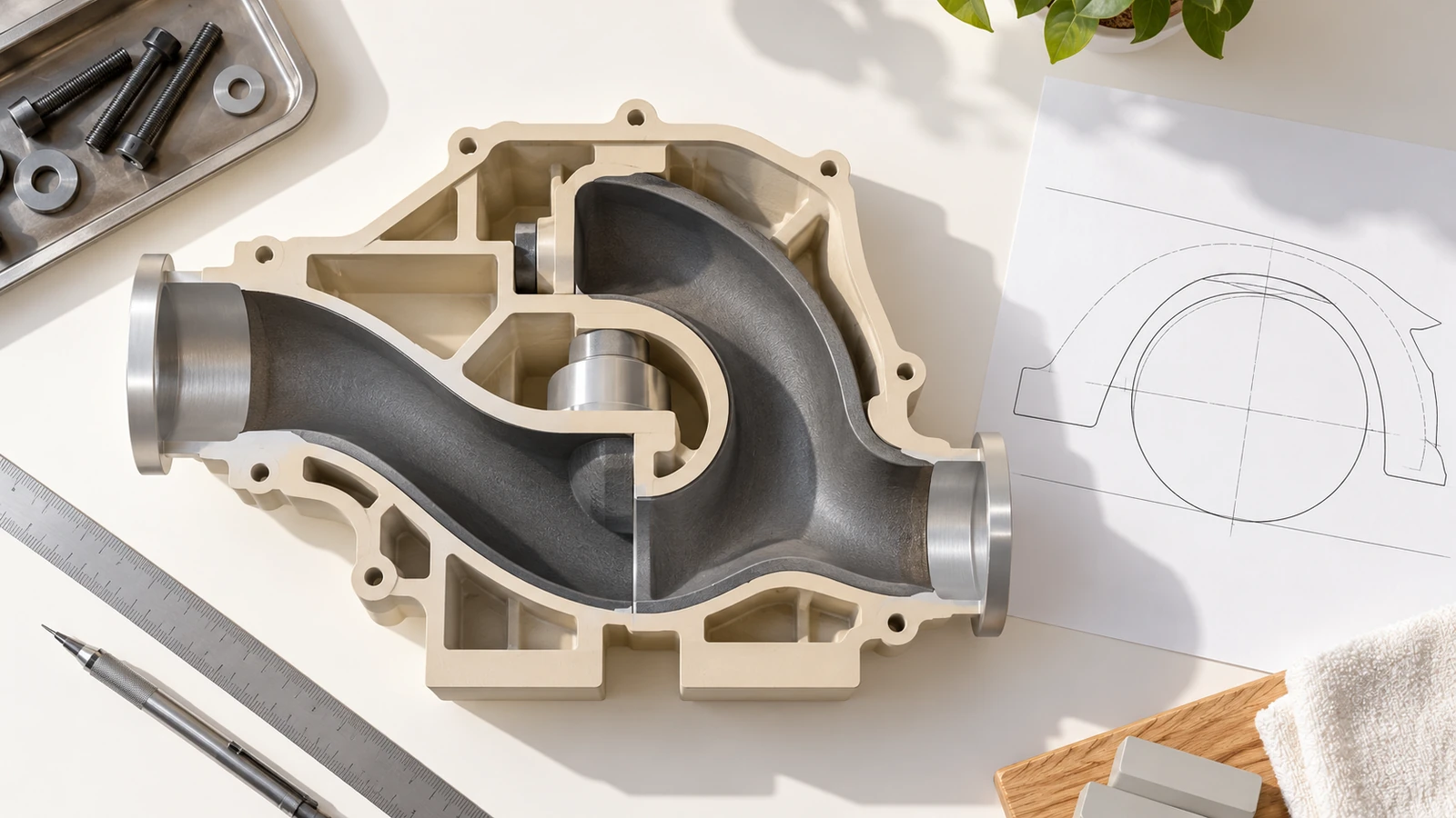
Wheel clearance is another reason to keep geometric relationships explicit. A bore or register may locate the rotating assembly relative to the housing, while a flange or backplate interface controls how the housing joins the next component. The drawing should show the datum references and the controlled relationships between these features. A bore diameter alone does not describe its position or orientation relative to a mounting face.
For an early prototype, decide which internal contours need to reproduce the intended geometry and which may be simplified for fit or packaging checks. A simplified path may be entirely appropriate for a clearance prototype, but it should not be represented as a validated aerodynamic or thermal design. Label the model revision and test purpose so later teams know what the part can and cannot demonstrate.
Account for the blank before planning the cut
Machining behavior depends on the actual blank, not just the CAD surface. Compressor-side parts may use one material route while turbine-side components may use heat-resistant cast alloys. A cast blank brings its own allowance, surface condition, and local stock variation. A billet or machined-from-solid prototype presents a different material distribution and may not reproduce the stiffness or cost of the eventual production part.
For a casting, identify which regions must clean up and how much stock is expected on each critical face. If stock varies, a setup that references an as-cast surface may shift the finished geometry from one blank to another. The process plan can instead establish machined datums first or use a locating feature designed into the blank. That decision belongs in the drawing and manufacturing review.
For a prototype cut from solid stock, make sure the evaluation goal justifies the extra material removal and the resulting part is not being used to make unsupported claims about production-route performance. If the product is moving toward a cast design, prototype machined surfaces can still validate interfaces and assembly access while casting-specific questions remain for a representative blank.
Material callouts should include the required grade and condition where known. “Aluminum” or “heat-resistant alloy” may be too broad for an accurate quote. The buyer should specify whether substitutions require approval and what material documentation accompanies the part. Do not infer a grade from the component name or a screenshot.
Support thin sections without distorting the part
Thin walls can vibrate under cutting forces, move as adjacent material is removed, or deflect under clamping. These effects are more likely to complicate a housing with a large curved cavity and uneven support. The right response is not simply to reduce feed or add more clamps. Review tool engagement, the order of roughing and finishing, the locations used for support, and how the part will be measured after release.
Where the design allows, temporary stock or added machining tabs may provide support during early operations. Such features must be planned and removed without damaging the finished surface. If the part is too flexible for the selected setup, a different blank, fixture, or sequence may be needed. This is why a supplier should review both the model and the manufacturing purpose before locking a process plan.

Roughing and finishing should be treated as separate stages when stock removal can change the part’s condition. Leave a controlled amount of material for finishing critical bores, registers, and sealing faces after the main cavity work. The specific allowance and sequence must come from the design, blank, and capability review; a generic number would not be reliable across different housings.
Plan inspection around concentric and sealing features
Inspection should address the relationship of the wheel-side register or bore to the mounting faces and other locating features. It should also cover sealing surfaces, bolt patterns, and port locations called out as functional. The inspection method must have access to the surfaces and a defined datum scheme. If an internal contour is difficult to reach, decide in advance whether it will be checked with a probe, a dedicated gauge, scanning, or another suitable method.
Measure the final condition after deburring and any specified finish. A burr at a port edge or a coating on a mating face can change assembly or clearance even if the pre-finish dimensions were acceptable. Note which features are measured before and after secondary processing, and record the part revision used for the report.
A prototype report should answer a specific question. Is the critical bore concentric to the mounting register? Does the flange pattern fit the manifold? Can the assembly be installed without interference? Keep the checks tied to the test purpose, and avoid implying that dimensional acceptance alone validates the complete turbocharger system.
What a useful RFQ should include
Send the exact component name, 3D model, dimensioned drawing, revision, material grade and condition, blank type if known, quantity, finish, and critical inspection requirements. Identify the mating components and the geometry that controls wheel, bearing, or manifold fit. State whether the requirement is a prototype, design iteration, or repeat order.
If the part includes several related housings, list them separately and distinguish which parts are included in the quote. Add questions about material alternatives, cast blank availability, finish, or measurement access rather than assuming every supplier interprets the package identically. The automotive CNC machining overview explains how process planning can change across prototype and production stages, while the automotive CNC parts guide provides a broader part-selection context.
Choose the next build from the evidence you need
A useful next build follows the unresolved engineering question. The same physical housing may need a different blank, machining extent, or inspection plan depending on whether the team is checking packaging, assembly, or a production-like interface.
| Open question | Build emphasis | Evidence to request |
|---|---|---|
| Will it fit the package? | Envelope, ports, mounting faces, tool access | Fit review against the defined mating geometry |
| Are the rotating interfaces aligned? | Registers, bores, datums, clamping state | Dimensional report tied to the released drawing |
| Will the production blank machine consistently? | Representative cast stock and cleanup allowance | Results from the intended blank and route |
Do not ask one prototype to prove all three questions unless it was planned to do so. State the build purpose in the RFQ, define the material and inspection scope, and keep conclusions within that scope. Strong automotive turbocharger housing machining is a coordinated handoff between the part definition, blank, setup, and evidence—not a promise that one route suits every housing.

