


A transmission shift fork does not transmit engine torque, but its contact surfaces decide whether a synchronizer sleeve reaches the position the design expects. That makes automotive transmission shift fork machining a geometry-and-interface problem, not simply a matter of cutting the outline. The fork must clear neighboring parts, guide the sleeve without binding, and keep both contact pads aligned under the assembly’s specified motion.
For a prototype or a design revision, the useful manufacturing question is: which surfaces actually control engagement, and how can those datums survive forming, casting, heat treatment, and finish machining? Start there, then choose the process route around the part’s material, volume, and drawing requirements.
Contents
- What the fork must control in the transmission
- Which features deserve functional datums
- Choosing a blank and process route
- Sequencing automotive transmission shift fork machining
- How to inspect contact geometry and fit
- What to send with a quotation request
- Frequently asked questions
What does a shift fork have to control?
The fork converts movement from a shift rail, selector, or actuator into axial movement of a sliding sleeve. Depending on the transmission architecture, the fork may contact a sleeve groove through pads, wear surfaces, or attached inserts. Those interfaces influence travel, clearance, and whether the sleeve can move without excessive side load.
This function creates several linked dimensions: the distance between the contact faces, their symmetry about the fork center plane, the relationship between the fork and its rail or pivot feature, and the clearance to adjacent gears or housing walls. A part can meet its outside profile dimensions and still fail assembly if the two pads are not positioned consistently relative to the mounting datum.
It is important not to infer operating loads or allowable wear from a generic part name. Manual, automated, dual-clutch, and oth
er transmission layouts place different demands on fork geometry and materials. The released drawing and assembly model are the governing references.
Which features should become the datums?
Choose datums that represent how the fork is located and loaded in the real assembly. A datum scheme often begins with the rail bore, pivot interface, or another locating feature, then relates the sleeve-contact faces and selected mounting surfaces to that reference. The exact scheme depends on the design; a convenient edge is not automatically a functional datum.
Use the 3D assembly to identify the surfaces that touch, slide, or constrain motion. Then compare them with the 2D drawing and mark the dimensions that control engagement. If the drawing does not identify the contact surfaces or their relationship, resolve that ambiguity before toolpath programming. Otherwise, suppliers may choose different inspection setups and report numbers that are not comparable.
| Feature group | Why it matters | Review question |
|---|---|---|
| Sleeve-contact faces | Control engagement position and contact symmetry | Are both faces related to a common center plane or datum? |
| Rail bore, pivot, or mounting interface | Locates the fork in the mechanism | Which feature is the primary assembly locator? |
| Clearance profile | Prevents interference through the travel path | Is clearance checked in th |
e assembled envelope?
Edge breaks and surface conditionAffect handling, contact, coating, and burr riskWhich edges are functional?
How should the blank and process route be selected?
Shift forks may be produced from formed or stamped metal, cast or forged blanks, or machined stock, depending on design and production economics. These routes are not interchangeable. A thin fork with a broad, mostly planar shape may suit forming; a three-dimensional body or prototype with changing geometry may need another route. A near-net blank can reduce material removal, but its stock allowance, distortion, and datum surfaces must be considered before finish operations.
For development quantities, CNC machining can accommodate geometry changes without immediate production tooling. For a stable high-volume program, forming or casting may be more suitable, with machining reserved for controlled bores, faces, or contact features. Compare total route cost and validation effort, not just raw stock cost or machine time.
Automotive sourcing teams can use the automotive prototyping and manufacturing overview to connect the part’s development stage with the process discussion. Where the drawing calls for machined datums or bores, see CNC-Bearbeitungsdienstleistungen. These links do not replace a part-specific DFM review.
What sequence helps prevent geometry drift?
A robust sequence separates stock removal from final control. First establish a stable locating reference on the blank. Remove bulk material while enough stock remains to support the fork arms and pads. If heat treatment, stress relief, or coating is specified, account for its effect on distortion and dimensions before deciding which features to finish early.
Next, create the functional locating feature and finish contact surfaces in a setup
that preserves their relationship. If both pads must be symmetric, a common setup or a fixture referencing the same datum can reduce setup-to-setup variation. Where multiple setups are unavoidable, document how the part is re-located and which surfaces are protected from clamping damage.
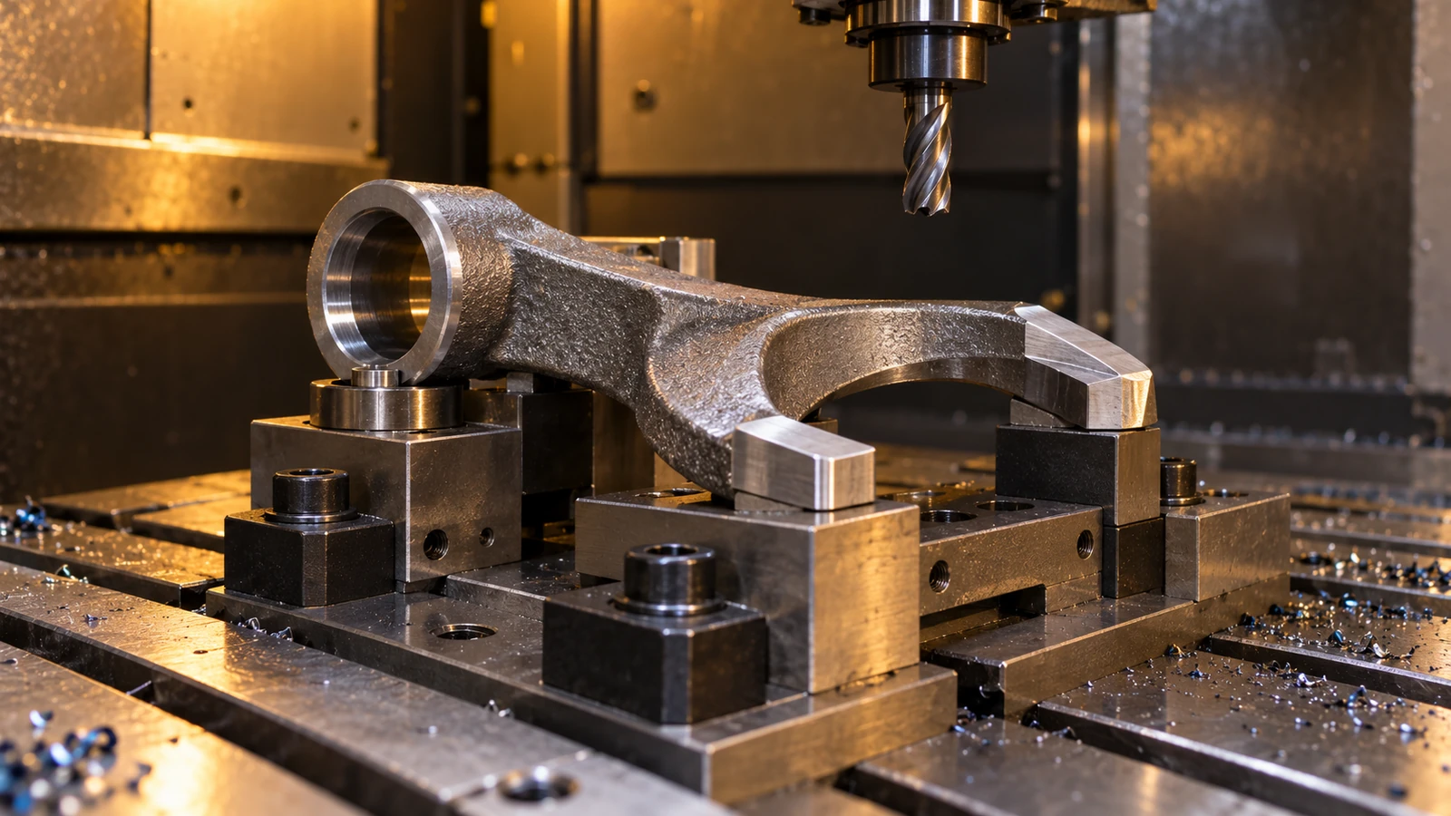
Tool access and stiffness matter because the fork arms can be slender. Clamping directly across a thin arm may deflect it during cutting; after release, the measured shape can move. Support points should resist cutting forces without marking a contact face. Toolpath order should avoid removing one side so aggressively that the remaining section loses support before its matching feature is cut.
How can inspection reflect the real assembly?
Inspection should answer whether the part meets its drawing and whether reported dimensions relate to assembly function. A coordinate measuring machine, dedicated gauges, or a combination may be appropriate, but the method must match the feature and tolerance. A CMM can map position and profile; a functional fixture can assess location and motion if the fixture itself is controlled.
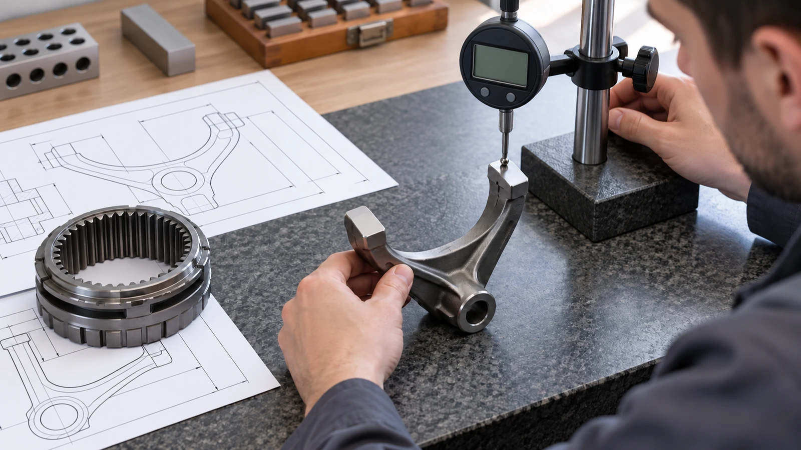
Measure critical dimensions from the agreed datum reference frame. For opposing contact pads, report their separation and relationship to the center plane rather than two unrelated surface coordinates. Inspect the rail or pivot feature in the same coordinate system when possible. On early prototypes, retain a fuller dimensional record so the design team can distinguish a geometry issue from a process issue.
Surface finish, burrs, and edge condition deserve explicit acceptance language where they touch a sleeve, retain lubricant, or approach another component. “Deburr all edges” may be insufficient if a functional edge must retain a defined radius. Do not assume polishing, coating, or heat treatment leaves a critical dimension unchanged; specify whether final measurement occurs before or after those operations.
What information should be included in an RFQ?
Send the latest 2D drawing and 3D model together, with revision identifiers. Include material and condition, target quantity, prototype or production phase, se
condary operations, inspection expectations, and any critical-to-function features not obvious from the model. State whether the supplier may propose a blank or process alternative, and identify which dimensions cannot change.
If samples exist, identify whether they are approved parts, worn parts, or reference geometry only. A sample can clarify form, but it cannot override a controlled drawing. For a process comparison, ask the supplier to separate tooling, blank, machining, finishing, inspection, and packaging assumptions so a volume change can be evaluated without rebuilding the estimate.
The purpose is not to add tight tolerances everywhere. It is to align the process and inspection plan with the surfaces that control gear engagement. That makes revisions easier to evaluate and gives procurement a clearer basis for comparing suppliers.
Frequently asked questions
Is CNC machining the normal production route for every shift fork?
No. Geometry, material, annual volume, tooling investment, and interfaces determine whether forming, casting, forging, machining, or a combined route is appropriate. CNC can suit prototypes and critical secondary features, but it is not automatically the lowest-cost route for stable high volumes.
Should both contact pads have the same tolerance?
Only if the design function and datum scheme require that relationship. Identify the surfaces that control sleeve engagement and define their relation to the locating feature. Uniform tolerance on every exterior surface can add cost without improving fit.
Can a sample replace an incomplete drawing?
A sample can support discussion, but it may include wear, prior modifications, or uncontrolled variation. Use it only as a documented reference and confirm final requirements in a released drawing or approved model.

