


An aircraft floor beam supports floor structure and transfers loads into the surrounding airframe. Its manufacturing challenge is not simply making an I-, C-, or closed-section shape. The beam must meet the geometry and interface definition while remaining accessible to cut, inspect, handle, and assemble. For a machined or fabricated prototype, the most important early decision is to distinguish the beam’s load-bearing role from adjacent frames, seat tracks, floor panels, and fittings.
This article is about the part-level design and manufacturing review. It does not specify aircraft structural allowables, repair methods, or certification requirements. Those belong to the approved design data and responsible engineering authority.
Separate the beam from the surrounding structure
Start with the assembly drawing and map the beam’s endpoints, supports, floor-panel contacts, and attachment fittings. A floor beam may span between frames or connect to adjacent structural members, while a fuselage frame follows a different structural path. Seat tracks and floor panels may attach to the beam but are not interchangeable with it. A clear article and drawing should preserve those distinctions.
Mark the critical interfaces: beam end fittings, floor support lands, holes or slots, and any local feature that transfers a concentrated load. Identify which surfaces locate the part in the aircraft assembly and which are secondary. This informs the datum scheme and prevents the supplier from holding a broad outer profile tightly while missing an attachment relationship that governs installation.
Part length and section variation can make setup planning important. A beam may have tapered webs, changing flanges, pockets, or local reinforcements. Show the overall envelope and the interface coordinates in a controlled frame. The aerospace design-for-machining guide is useful when reviewing datum strategy and access before the beam profile is finalized.
Choose a section that can be made and inspected
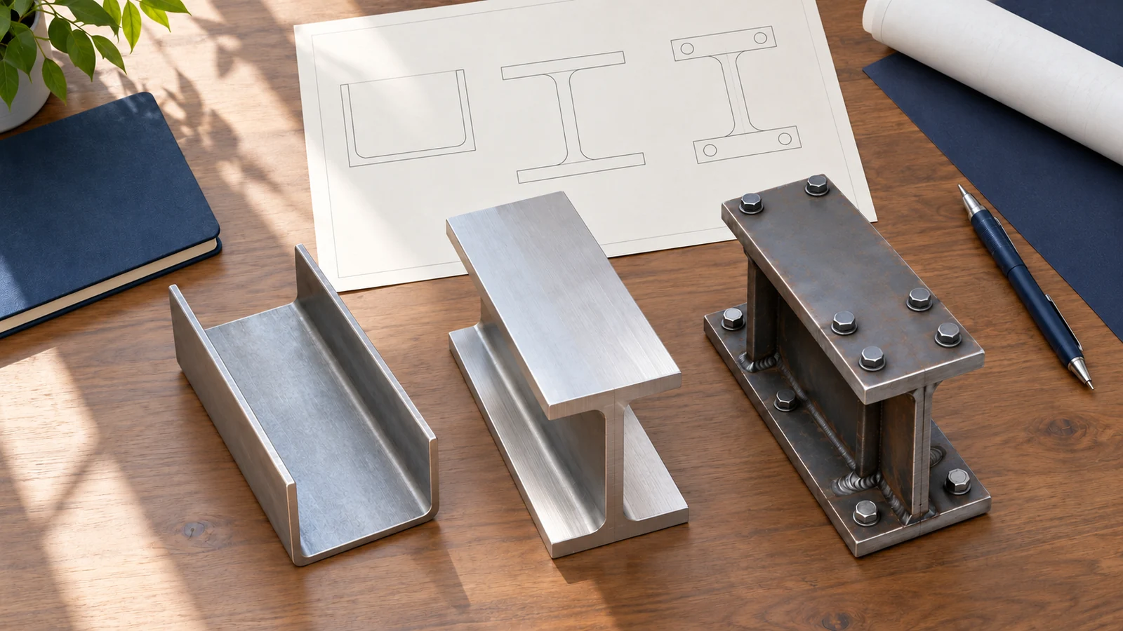
Section shape affects stiffness, weight, machining access, and how the part is supported. A deep channel can offer structural depth but limit access to internal faces. A thin web may reduce mass but deflect during cutting or measurement. A closed section can resist torsion but may require joining or special inspection access. The design choice should be validated by analysis and then reviewed for practical manufacture.
On a machined beam, deep pockets and thin residual walls can create long tool paths and unstable cutting. Uniform wall transitions, accessible corner radii, and sacrificial support features can make the operation more predictable. On a formed beam, bend radii, springback, edge quality, and feature position after forming need to be controlled. On a built-up beam, the joints and assembly sequence become part of the dimensional chain.
Do not use “lightweight” as a substitute for a defined requirement. Specify the profile, material, condition, and controlled features, then allow the manufacturing review to flag cost or access risks. If geometry is still evolving, a prototype can answer whether fasteners and panels fit, while structural validation remains separate.
Control attachments and local reinforcements
Floor beams often carry holes, slots, clips, brackets, or local doublers. These features can be easy to dimension individually yet difficult to relate across a long part. A coordinate table tied to a common datum may be clearer than a chain of dimensions from one end. If an end fitting is separately manufactured, define its alignment and joining requirements at the assembly level.
Fastener edge distance, access, countersink or counterbore geometry, and panel clearance should be reviewed against the real stack. A cutout that clears one component may interfere with wiring or a nearby fitting. If a slot permits adjustment, state the intended adjustment range and how the final installed location is controlled. Avoid implying that the supplier may adjust structural geometry without engineering approval.
For formed or joined structures, call out the manufacturing sequence where it affects the final interface: whether holes are made before or after forming, whether a fitting is installed before finish, and how the assembly is held for inspection. The site’s aerospace sheet-metal fabrication page can support discussions about formed profiles and process access.
Compare machining, forming, and built-up routes
CNC machining can support complex profiles and prototype revisions, particularly when a beam is short-run or has integral pockets and interfaces. A long monolithic beam may require specialized workholding, multiple setups, and careful planning to avoid deflection. Formed sheet or extrusion-based routes may reduce material removal for suitable geometry, but they introduce bend, section, and joining constraints. A built-up structure can separate functions but adds joints and tolerance stack.
Compare total manufacturing scope rather than only the primary operation. Include raw stock, cutting, forming, machining, joining, finishing, inspection, and packaging. A hybrid route may be attractive if only the interfaces require precision machining. If the part is intended for repeated production, assess repeatability and inspection access as well as prototype speed.
Use the aerospace manufacturing process overview to organize candidate routes, then select based on the current drawing and program constraints. Material substitutions or process changes should follow the design authority’s approval process.
Manage long-part distortion and handling
Long, slender components can move during machining, release from clamps, or transport between operations. Support points should prevent sag without imposing a shape that disappears after unclamping. A fixture that over-constrains the beam can create a misleading inspection result. The drawing or inspection plan should define the free-state or restrained condition for any critical straightness or profile requirement.
Roughing and finishing may need separate operations so major material removal does not leave the final interfaces exposed to later distortion. Whether a stress-relief step is permitted or required depends on the material, product form, and approved process. Do not prescribe it generically. Ask the supplier to identify where the geometry is most sensitive and how the plan will verify it after release from the fixture.

Protect long edges and attachment surfaces during handling. Dents, twist, or local damage can affect fit even when the machined features are correct. Packaging and support design should be considered part of the delivery plan, especially for thin-section prototypes.
Verify the beam in a useful datum scheme
Inspection should connect overall profile, end interfaces, mounting holes, and local features to the assembly datums. A single point-to-point length check is not enough if the beam must fit between defined supports and align multiple floor components. CMM measurement, scanning, templates, or fixture checks may each be useful depending on geometry and tolerance requirements.
For long parts, document how the beam was supported and where measurements were taken. If the feature is measured in a restrained state, define the restraint. If a profile is checked after forming or joining, state the condition and revision. Any special process or finish can affect the final dimension and must be included in the inspection sequence.
Inspection confirms specified geometry and records; it does not replace structural substantiation or aircraft-level approval. The aerospace quality and inspection guide can help define first-article evidence for a beam prototype or production part.
For the broader component-development context, the aviation and aerospace prototyping page connects the beam to the wider aircraft program while this article remains focused on its manufacturing interfaces.
Frequently asked questions
How is a floor beam different from a fuselage frame?
A floor beam primarily supports floor structure and related attachments, while a fuselage frame follows the surrounding body structure. They may connect, but their interfaces and load paths are distinct.
Is CNC machining always the best route for a floor beam?
No. Machining, forming, extrusion-based construction, or a built-up assembly may be considered. Length, section, material, quantity, and interface requirements determine feasibility.
Why does support condition matter during inspection?
A long beam can sag or distort under its own weight or fixture force. The measurement state must match the drawing requirement so reported geometry is meaningful.
Can a prototype validate structural performance?
Only if it is built and tested under the approved structural verification plan. A fit prototype answers packaging questions, not flightworthiness by itself.

