


An aircraft access panel looks simple until a technician has to remove it repeatedly, reach a hidden service point, and reinstall it without damaging the surrounding skin or hardware. The manufacturing question is not just how to cut a flat shape. It is how the panel, its opening, fasteners, edge treatment, and neighboring structure work together over the life of the assembly.
For a prototype or production-intent part, the drawing should make that relationship inspectable. Define the boundary, attachment method, allowable gaps, and service task before selecting a fabrication route. This keeps a lightweight cover from becoming a fit problem or an awkward maintenance step.
Begin with the service task
List what the panel allows someone to reach: a connector, inspection point, fluid fitting, actuator, or replaceable module. Then describe the actual service motion. A cover that lifts vertically may work in an open bay but fail where a harness or adjacent structure blocks the lift path. A hinged panel can improve access yet add hinge clearance, support, and retention requirements.
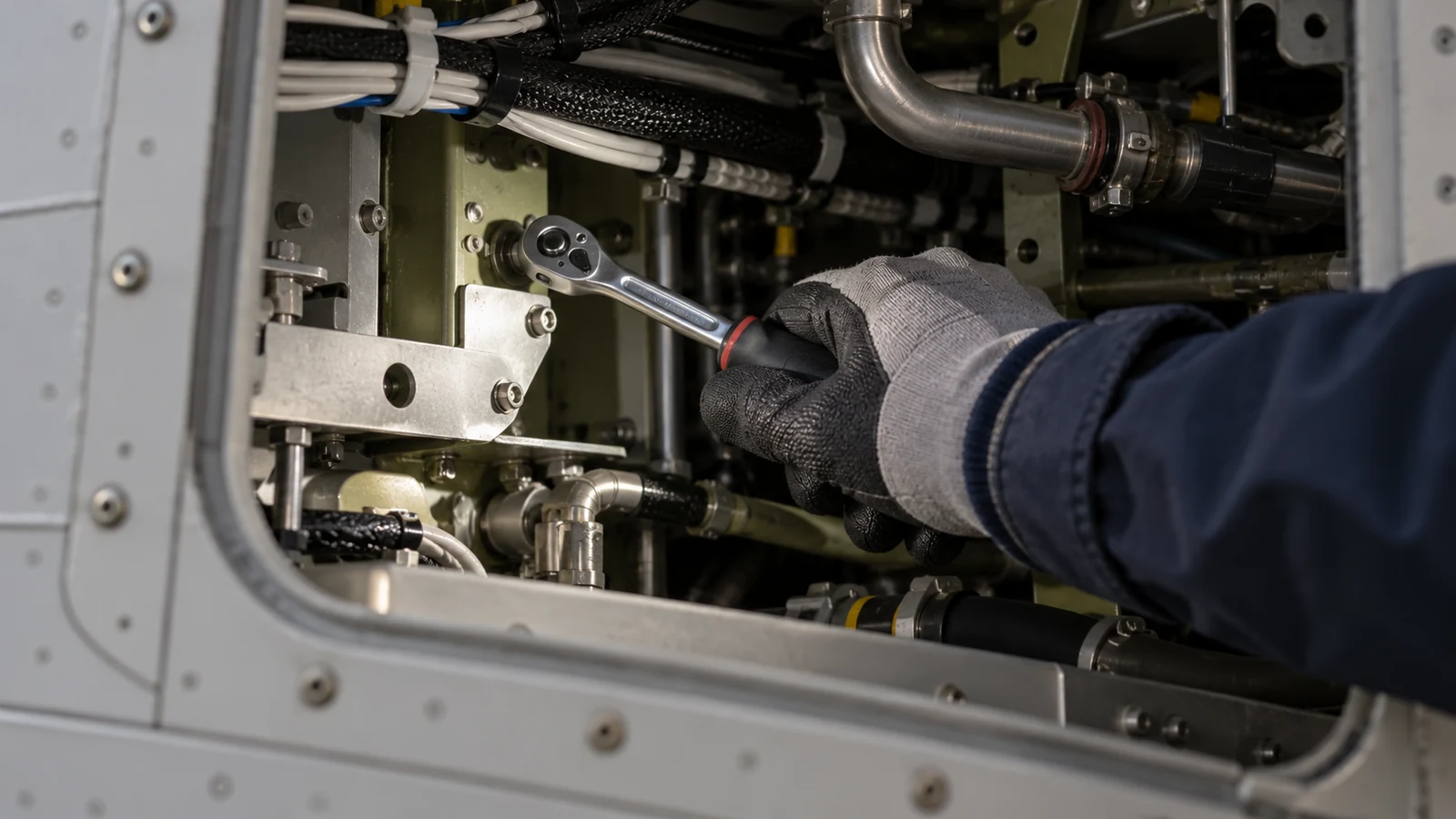
Capture the opening direction, tool envelope, hand clearance, removal sequence, and whether the panel must remain attached during service. These details influence the panel outline and fastener positions more than the nominal area. Where maintenance is performed in a constrained space, a simple physical mock-up can test access before the final material and finish are selected.
Do not use a manufacturing drawing to imply a service procedure that has not been reviewed by the responsible design team. The component supplier can identify manufacturability concerns, but the aircraft-level maintenance requirements and acceptance criteria remain controlled by the customer.
Treat the opening and panel as a pair
The opening defines the reference for panel fit. Establish which edges locate the panel and which edges simply provide clearance. If all sides are dimensioned as tight locating surfaces, normal forming variation, coating thickness, and assembly stack-up can make installation unpredictable.
Use datums that reflect how the panel is installed: a primary seating surface, a locating edge or feature, and a fastener pattern that holds the panel in place. Dimension the panel-to-opening gap where it matters for appearance, airflow, sealing, or inspection. If the opening is produced by another supplier or assembly operation, identify the measurement condition and tolerance ownership rather than assuming both parts share a perfect nominal outline.

Curved or locally reinforced skin requires special attention. A flat panel placed over a shaped surface can rock, bridge, or pull down unevenly when fasteners are tightened. Define the contour or contact condition and decide whether the panel must conform, sit on a flange, or use a separate support ring.
Choose fasteners and edge details deliberately
Fastener selection changes hole size, countersink geometry, edge distance, tool access, and panel removal time. The drawing should identify the fastener family or interface standard when available, plus the required head relationship and any flushness requirement. If hardware is customer-supplied, make that clear before quoting.
Thin sheet edges can distort during cutting and finishing. Burr direction, corner radius, local return flanges, and protective edge treatment should be considered together. A sharp internal corner may concentrate stress or complicate finishing; a generous radius may conflict with the mating opening. State the functional edge condition instead of relying on an ambiguous note such as “deburr all edges” when a particular edge has a critical fit or handling role.
For a sealed panel, define the sealing land, gasket compression strategy, and surface condition. Avoid assuming a coating or sealant can compensate for a poorly controlled flange. For a non-sealed cover, do not add sealing features that complicate manufacturing without a clear requirement.
Select a fabrication route from geometry
A flat, low-volume cover may be efficiently cut from sheet and finished with simple edge operations. A formed panel adds bend sequence, springback, tooling access, and flange consistency to the plan. A machined panel can suit a thicker or more locally detailed design, but material removal, stock size, and weight should be reviewed against the function. A hybrid assembly may combine a formed skin with a machined frame or inserts, adding joining and inspection considerations.
Compare options using the drawing’s true constraints: curvature, thickness, local ribs, formed returns, holes near bends, finish requirements, quantity, and revision stage. The best route is not necessarily the one with the fewest process steps; it is the one that can repeatedly meet the interface requirements and be inspected with a clear reference scheme.
For broader context on the available aerospace manufacturing processes, distinguish a prototype route from a released production process. A prototype can answer fit and access questions without establishing flight qualification or production approval.
Use prototypes to reveal access problems
Early prototypes are useful for checking reach, removal direction, fastener tool clearance, and panel handling. A simplified model can validate envelope and opening geometry; a material-representative build is more useful when stiffness, formed returns, or surface interaction matters. Record what the prototype does and does not represent so its results are not mistaken for qualification evidence.
Check the panel in the surrounding assembly, not only on a bench. Confirm it can be installed without forcing, the fasteners remain accessible, and removal does not require moving unrelated components. Review the panel with the maintenance task owner and the design authority before freezing the geometry.
Revision control matters: identify the drawing revision, model state, hardware assumptions, and any deliberate prototype deviations. A small change to a neighboring bracket can alter access even if the panel drawing itself remains unchanged.
Inspect fit in the installed condition
Inspection should separate the panel’s own dimensions from its assembled fit. Verify the profile, hole locations, flange geometry, and edge condition against defined datums. Then evaluate gap, flushness, or contact in the installed condition using an agreed fixture or representative mating surface.
Do not hide a fit issue by tightening fasteners until the panel conforms. That can mask a contour mismatch and introduce stress or damage. Define whether the part is checked free-state, restrained, or installed, and specify the sequence if those states produce different measurements.
Material and finish records should match the procurement and drawing requirements. The relevant aerospace materials page can help frame material selection, but the approved grade, condition, and finish must come from the controlled specification. Inspection documents should not claim certification beyond the records actually supplied.
A practical drawing and RFQ checklist
- Panel and opening models or drawings at the same revision.
- Datum scheme and installed measurement condition.
- Fastener type, supply responsibility, head condition, and access constraints.
- Required gap, flushness, sealing, or contact criteria.
- Material, temper or condition, finish, and edge requirements.
- Quantity, prototype purpose, and expected revision status.
- Inspection records and acceptance evidence requested for the build.
Clear inputs let a supplier identify risks before cutting material. If an interface is still under design, mark it as provisional rather than allowing assumptions to become hidden acceptance criteria.
Frequently asked questions
Should an access panel be designed as a flat part?
Only when the surrounding surface, service task, and stiffness needs allow it. Contoured skins or sealing requirements may call for formed geometry or a supporting frame.
What should be checked on the first prototype?
Prioritize installation direction, tool clearance, service reach, fastener access, and fit against a representative opening. These checks can expose design issues before finish details are finalized.
Does a prototype prove aircraft-level qualification?
No. A prototype can verify specified design questions, but qualification and release depend on the applicable program requirements, controlled processes, and authorized acceptance evidence.
For program context, this component belongs within the wider aviation and aerospace prototyping scope. When the service task, opening, attachment, and inspection condition are defined together, an access panel becomes a predictable interface rather than a cosmetic cover that only fits under ideal bench conditions.

