


An aileron bellcrank changes the direction and ratio of movement between control-system links. Its pivot axis and arm-hole locations form a controlled kinematic relationship. A machined bellcrank can meet every hole diameter and still be wrong if its arm planes are twisted or the pivot axis is shifted relative to the linkage points.
The aircraft’s design authority defines travel, load cases, allowable play, and rigging. Manufacturing should preserve the released geometry and provide measurements of the features that control the mechanism. The focus here is the component’s datum scheme, machining sequence, and inspection—not flight-control design.
Contents
- Read the mechanism before the part drawing
- Control arm geometry from a shared datum
- Treat the pivot as a functional interface
- Protect load-bearing transitions
- Keep machining setups tied to geometry
- Measure the bellcrank in its working orientation
Read the mechanism before the part drawing
Identify the input and output links, pivot support, control-surface connection, and full range of travel. The bellcrank may redirect a pushrod, change a motion ratio, or package a linkage around structure. Those functions should be clear from the assembly model and controlled interface data.
Review both travel limits and intermediate positions. An arm, fastener, rod end, bearing housing, or nearby panel may interfere only at one angle. If the part is asymmetric, show its orientation and installation side. Do not assume it is reversible because its outline looks balanced.
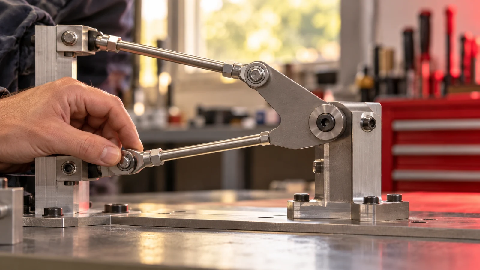
The system designer should identify which dimensions affect the control response. Manufacturing can then distinguish critical relationships from nonfunctional edges and plan inspection accordingly.
Control arm geometry from a shared datum
Define the angle between arms and the position of every linkage hole relative to the pivot axis. If the hole location controls the motion ratio, tolerance it to a functional datum rather than an arbitrary outer edge. For a nonplanar part, section views should explain how arm planes relate to each other.
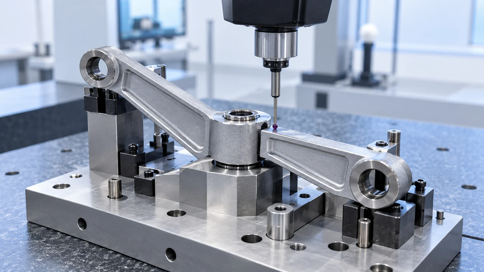
Arm thickness, hole edge distance, and local contour follow the approved structural design. Do not change an arm length or hole position to make a linkage fit without review. Even a small shift can alter leverage or load distribution.
Where multiple holes provide alternate rigging positions, identify each position and the released configuration. Inspection should report the actual locations relative to the pivot datum rather than merely confirm hole sizes.
Treat the pivot as a functional interface
The pivot may use a bushing, sleeve, bearing, pin, or another approved arrangement. Define the bore, fit, axis orientation, retention, and condition after installation. Bore diameter alone does not establish pivot function; its relationship to the linkage holes matters too.
Clarify whether a bushing is installed by the manufacturer or during final assembly. Pressing a bushing can affect bore size or arm spacing. If a coating is applied, define masking or post-finish machining for the bearing feature and sequence the inspection accordingly.
Assembly play and articulation limits come from the control-system definition. Smooth movement by hand is not a measurement of acceptable free play, and a tight-feeling joint does not prove correct alignment. Use the controlled procedure.
Protect load-bearing transitions
Fillets, arm roots, cross-holes, and thickness transitions influence local stress and fatigue behavior. Structural analysis defines their geometry and material condition. A cutter radius proposed for manufacturability must be accepted by engineering before the drawing changes.
Control burr removal around linkage holes and the pivot bore. A burr can interfere with a pin or bearing surface, while aggressive blending may remove material from a critical edge. State which edges are functional and how any permitted break is assessed.
Material, temper, traceability, and finish must match the approved aircraft specification. Do not substitute a more convenient alloy based on a generic strength comparison.
Keep machining setups tied to geometry
Workholding should support thin arms without bending them, while exposing the pivot and linkage features to stable tool paths. If these features are machined in separate operations, the datum transfer must preserve their relationship. Plan deburring and inspection so finished bearing surfaces are protected.
A plate or billet route may suit a one-piece machined design, depending on the released geometry. An assembled design can simplify some features but adds a joint and another alignment stack. Compare routes against the controlled drawing rather than changing geometry to suit an assumed process.
Jucheng’s CNC machining capability can be assessed for the specified material, tolerances, and inspection plan. The aluminum alloy material page is only an initial machinability reference; the aircraft callout controls.
Measure the bellcrank in its working orientation
Inspection should relate the pivot axis, arm planes, and linkage-hole positions to the same datum structure used by the assembly. A CMM or fixture may be appropriate, but the setup must reproduce the functional orientation. Record the fixture and support condition when the arms are thin or compliant.
Recheck features that may change after coating or bushing installation. First-article records should include revision, material traceability, critical dimensions, and approved deviations. A deviation that shifts a linkage point needs formal disposition before assembly.
System rigging verifies travel, direction, clearance, and approved response. These checks are distinct from component inspection. A dimensional report should state what was measured and should not claim aircraft-level performance.
A bellcrank is a measured motion relationship
Reliable aircraft aileron bellcrank machining preserves the pivot axis and arm geometry that define linkage movement. Clear datums, stable setups, controlled material, and inspection in a meaningful orientation make integration repeatable without relying on force or adjustment to hide a mismatch.
Use a repeatable inspection sequence
A practical inspection sequence begins with the raw material record and the part revision, then verifies the primary datum surfaces before measuring the pivot and linkage features. This order helps identify whether a later measurement issue comes from the part, the fixture, or an unstable setup. Record the condition after each process that can affect geometry, such as heat treatment, coating, or bushing installation.
For a first article, compare the measured arm locations with the controlled model and note how the part was oriented. If the bellcrank is inspected in a fixture, confirm that the fixture does not preload or twist the arms. Where a critical axis is difficult to access, agree on a qualified alternate measurement method before production rather than improvising after the part is complete.
Keep the data useful to assembly: report the pivot axis and linkage-hole positions in a common coordinate frame, identify any allowed adjustment, and link the record to material traceability. This creates evidence that can be compared across replacement parts and helps distinguish a component variation from a rigging issue.

