


An aircraft torque tube is a rotating mechanical member that transfers angular motion between locations in a flight-control linkage. Its manufacturing challenge is not simply producing a straight cylinder: the tube must preserve the relationship between its locating surfaces, attachment features, and the mechanism that receives its motion. If those relationships drift during machining or inspection, a part can meet isolated dimensions yet fail to assemble as intended.
For a new component or prototype, the released drawing and program-specific acceptance criteria remain controlling. A supplier should not infer an aircraft’s design intent from a generic sketch, change a flight-control dimension without approval, or treat a machined sample as evidence of airworthiness. The useful question is narrower and practical: what must be defined so the manufactured tube can be checked against the interfaces that matter?
Contents
- Start with the motion path
- Choose datums around assembly, not convenience
- Plan machining before thin features move
- Make joint features inspectable
- Select material from the released specification
- Build an inspection plan around functional relationships
- Give the supplier a complete handoff package
- FAQ
Start with the motion path
Before discussing machine operations, map how motion enters and leaves the tube. One end may connect to a lever, quadrant, crank, or other linkage feature; another may connect to a second control element. The exact arrangement varies by aircraft design. The drawing should identify the surfaces that locate the part, the features that transmit torque, and the allowable movement or clearance at each joint.
This functional map prevents a common quoting problem: a supplier sees a long cylindrical part with holes and slots, while the design team sees a controlled relationship between multiple linkages. Those are not equivalent descriptions. Add a datum scheme, identify the mating hardware, and clarify which dimensions are reference-only versus acceptance-critical. If an interface is controlled by a separate assembly drawing, include that drawing or a controlled extract with the RFQ.
Die Aviation & Aerospace manufacturing page describes the site’s aerospace prototyping and parts-manufacturing scope. It is a useful starting point for a project discussion, but the customer’s drawing and quality clauses still define what the specific part must satisfy.
Choose datums around assembly, not convenience
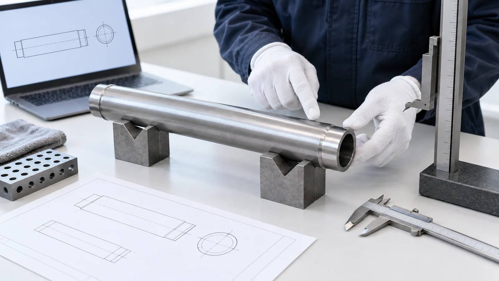
A tube can be dimensionally close and still be difficult to install if the datum scheme does not represent how the component is held in the aircraft mechanism. A practical drawing review asks three questions:
- Which cylindrical surface or bearing seat establishes the rotational axis?
- Which end face or shoulder controls axial location?
- Which hole, flat, spline, slot, or lever feature sets angular orientation?
When the drawing makes those answers explicit, both machining and inspection can use a consistent reference frame. When it does not, teams may measure each feature from a different setup and then discover that the combined position is uncertain. That uncertainty is especially relevant for long parts, where a small angular error at one end can become a noticeable positional difference at a distant interface.
Avoid adding tighter tolerances merely to make the drawing look more demanding. Tightening unrelated dimensions can raise cost without improving assembly. Instead, identify the functional relationships—such as coaxiality, perpendicularity, true position, or angular indexing—that control the linkage, and assign tolerances only after the design authority confirms them.
Plan machining before thin features move
Torque tubes may combine a long cylindrical body with cross holes, end bores, keyways, flats, or local brackets. The actual feature set depends on the design. Each secondary operation can introduce a new clamping condition, and each clamping condition can affect the relationship between the tube axis and the added feature.
A robust process plan typically separates reference creation from feature completion. The initial setup establishes the rotational axis and end reference. Turning or boring operations create the primary cylindrical geometry; milling and drilling then produce the specified interfaces while preserving a controlled reference to the axis. If opposite ends require work in separate setups, the transfer method and re-location features should be planned before production begins.
Long, slender parts also need support appropriate to their geometry and material condition. Excessive clamping force can distort a thin wall; insufficient support can allow vibration or deflection. The correct choice depends on length-to-diameter ratio, wall thickness, material, tool reach, and the drawing’s limits. A supplier should review these conditions during manufacturability planning rather than promise that one generic setup works for every torque tube.
Hier kommt CNC turning and milling may be combined, depending on the approved geometry. The process choice should follow the drawing, not the desire to advertise a particular machine configuration.
Make joint features inspectable
The most important details are often not the largest surfaces. A cross-hole location, spline phase, flat orientation, or bearing-seat transition can determine whether the tube connects correctly to adjacent hardware. Those features should be designed and documented so that they can be measured without ambiguous fixturing.
For example, if angular indexing matters, define the reference feature and the measurement method or acceptance datum. If a hole is intended for a pin, specify the relevant size, position, and edge condition rather than leaving the fit to visual judgment. If a shoulder controls axial location, identify the surface finish or contact requirements only when the design authority has specified them.
Deburring is another controlled operation, not cosmetic cleanup. Burrs around cross holes or slots can interfere with assembly, create loose material, or complicate inspection. But a supplier should not alter a designed edge break or remove material from a load-bearing transition without authorization. The drawing should separate mandatory edge conditions from general deburring notes.
Select material from the released specification
There is no universal “best” torque-tube material. The correct choice depends on the aircraft program’s approved material, temper or heat-treatment condition, load case, environment, joining method, and inspection requirements. Aluminum alloys may be considered where low mass and the design’s strength requirements align; steels or titanium alloys may be specified for other combinations of stiffness, fatigue, wear, or environmental demands. Those are design trade-offs, not permission for a supplier to substitute material.
Procurement documents should identify the material designation, product form, condition, applicable standard revision, and required certification records. If the drawing references an obsolete or ambiguous designation, resolve it with the customer’s engineering authority before purchasing stock. The CNC machining materials library can help a buyer review broad material categories, but it does not override the part’s controlled specification.
Build an inspection plan around functional relationships
Inspection should answer whether the part reproduces the reference geometry and the interfaces that control assembly. A useful plan may combine calibrated gauges for straightforward diameters, a coordinate measuring machine for positional relationships, and a suitable fixture or reference mandrel for long-axis checks. The exact method depends on the drawing and measurement uncertainty; do not assume a single instrument can verify every characteristic.
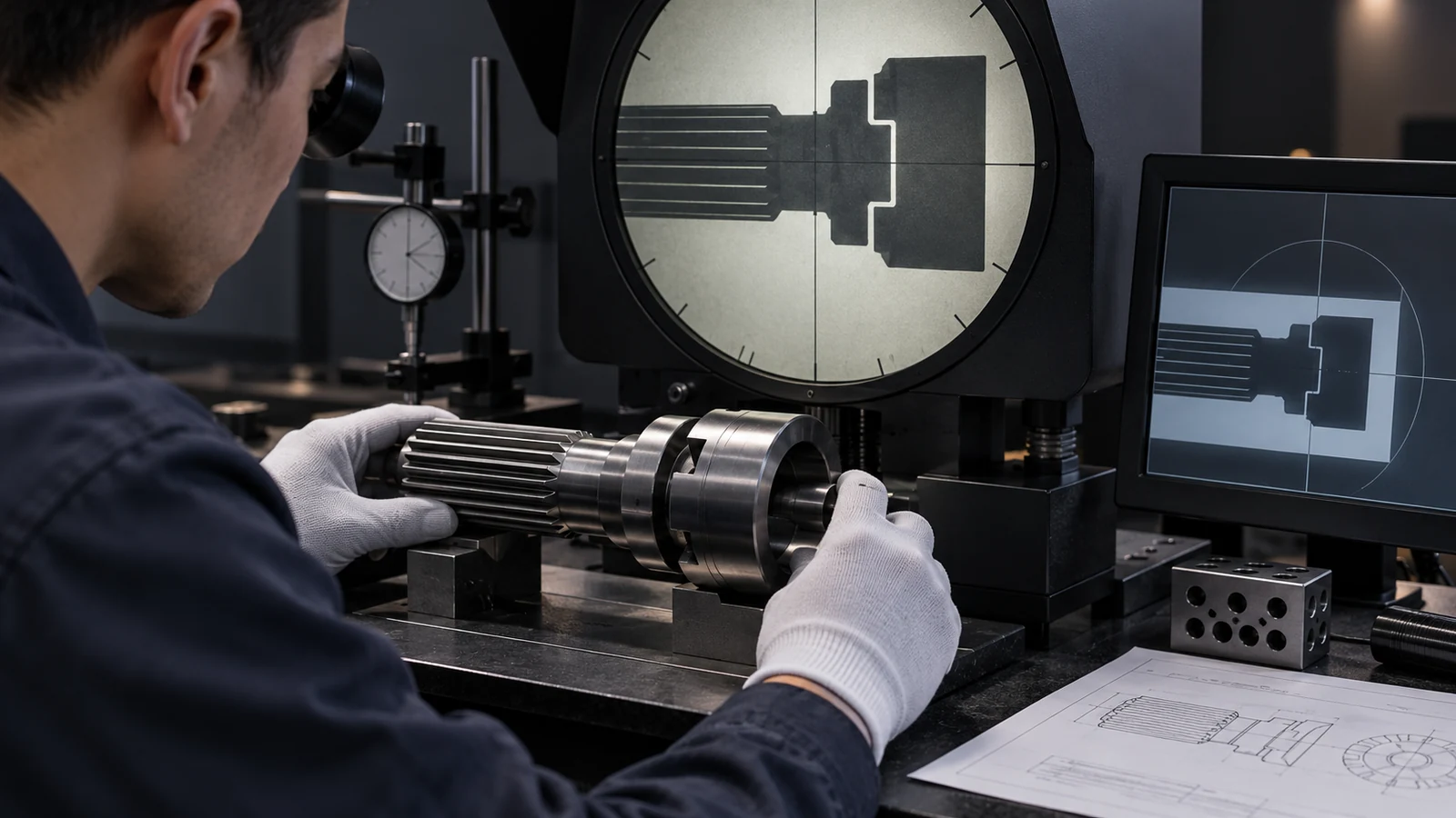
Before cutting material, agree on which characteristics appear in the inspection record. Typical candidates include overall length, bearing or journal diameters, runout relative to the primary axis, cross-hole location, slot or flat orientation, and specified edge conditions. Where a characteristic is critical but difficult to measure after machining, plan its inspection while the feature is still accessible.
First-article evidence should be tied to the current drawing revision and lot identity. A measurement report without revision control can be hard to interpret later. Jucheng’s quality assurance information lists examples of dimensional, material, and first-article documentation; project-specific deliverables still need to be agreed in the purchase order or quality clauses.
Give the supplier a complete handoff package
A clear RFQ package reduces assumptions. Include the controlled 2D drawing, 3D model if applicable, revision and effectivity, quantity, material and condition, finish or heat-treatment requirements, inspection characteristics, documentation expectations, and any customer-approved deviations. Identify whether the request is for an engineering prototype, a fit-check part, a development lot, or production hardware. These stages can have different acceptance evidence even when the geometry is similar.
Ask the supplier to flag unclear datums, inaccessible measurements, potential distortion, and features that may need a process sequence decision. Require questions to be resolved before they become undocumented shop-floor assumptions. If the design changes after a first article, define how the revision change affects stock, setup, inspection, and records.
FAQ
Is an aircraft torque tube only a turned part?
Not necessarily. A cylindrical body may require turning, but holes, slots, flats, splines, or attachment features can add milling, drilling, and secondary inspection. The released geometry determines the process plan.
Can a supplier choose a different alloy to improve machinability?
No—not without approval from the design authority. Material and condition are controlled requirements and may affect structural substantiation, traceability, and acceptance.
Does a dimensional inspection report establish airworthiness?
No. A report documents measured characteristics against defined requirements. Aircraft-level approval, installation, and airworthiness decisions belong to the responsible program and regulatory processes.
What should be checked first when a torque tube does not assemble?
Compare the controlled drawing revision, datum references, mating-part interfaces, angular indexing, and measurement method before changing the part. Do not remove material or modify a flight-control interface without engineering authorization.
Fazit
Reliable aircraft torque tube manufacturing starts with the motion path and datum scheme, then carries those references through machining, deburring, and inspection. The most useful supplier handoff makes mating interfaces measurable and keeps material, revision, and acceptance requirements controlled. That approach does not replace aircraft design approval; it gives engineering and procurement a clearer way to obtain a part that can be evaluated against the approved definition.
Source note: Functional description follows the FAA Airframe Handbook’s discussion of torque tubes in mechanical flight-control systems. This article is manufacturing-planning guidance, not maintenance or airworthiness instruction.

