


An aircraft bleed-air duct flange is the interface where duct sections, valves, or equipment connect within a hot-air system. It must maintain the defined sealing geometry while transferring mechanical loads and accommodating the installation arrangement. A flange that fits its bolt pattern may still leak or distort if its face, seal groove, material, finish, or assembly sequence is not controlled.
The aircraft system authority defines temperature, pressure, fluid compatibility, seal selection, and acceptance criteria. Manufacturing should not infer those values from a generic duct application. This guide focuses on drawing and process questions that help produce a verifiable flange interface.
Contents
- Gather the system inputs before detailing the flange
- Define the sealing face and seal interface
- Control the bolt pattern and assembly access
- Account for thermal movement and materials
- Coordinate duct forming and flange machining
- Inspect the finished sealing interface
- Prepare the release package
Gather the system inputs before detailing the flange
Identify what the flange connects: another duct section, a valve, a manifold, or an equipment port. Obtain the controlled mating interface, seal type, system environment, material specification, installation orientation, and acceptance plan. The design authority should define allowable leakage and any pressure or thermal test required at assembly level.
Clarify whether the flange is integral to a duct, welded or brazed on, bolted as a separate fitting, or formed from sheet. These constructions affect distortion, inspection access, and the location of the final sealing face. The drawing should reference the approved joint configuration rather than relying on a product rendering.
Check the system envelope and adjacent structure. Duct routing may be constrained by nearby equipment, thermal protection, wiring, or access panels. A flange that is machinable alone may not be installable once the duct is bent and the aircraft structure is closed.
Define the sealing face and seal interface
Specify the sealing surface in a way that identifies the controlled face, finish, flatness or profile requirement, and relationship to the duct centerline or mating datums. If a groove or seal land is used, define its width, depth, location, and edge condition from the approved design. Do not substitute a generic groove profile based on a common seal size.

Seal material and geometry are system-level selections. They depend on temperature, pressure, fluid, motion, and service life. The flange drawing should identify the approved seal or reference the assembly specification, but the machine shop should not choose an elastomer or sealing compound from general catalog data.
Be careful with surface treatment and paint. A coating on the sealing land can change dimensions or contact behavior. Define which surfaces are masked, whether the seal contacts a bare or treated surface, and how post-finish geometry is accepted.
Control the bolt pattern and assembly access
The bolt pattern should be related to the sealing interface and the mating component. A pattern that is locally dimensioned from an outside edge may not preserve concentricity or alignment to the duct. Identify the datum scheme and specify which holes locate and which provide clearance.
Review fastener access across the assembly sequence. A flange may be easy to bolt before nearby brackets are installed but inaccessible afterward. Check wrench clearance, nut retention, inspection visibility, and whether the duct can be removed without disturbing unrelated equipment.
Fastener preload and tightening sequence can influence sealing, but these values belong in the approved assembly procedure. Do not place an assumed torque on the part drawing. Ensure the design provides enough space for the specified tools and that the flange can be supported without bending the duct.
Account for thermal movement and materials
Bleed-air systems can experience temperature changes that affect duct length, flange alignment, seal compression, and support loads. The magnitude and direction depend on the system’s defined operating conditions, route, material, and structure. Thermal analysis should establish which movement the joint must accommodate.
Consider material compatibility at the flange, duct, fasteners, and seal. Differences in expansion or stiffness can change joint behavior. The approved materials and process specifications govern; a familiar stainless or nickel alloy designation alone does not prove suitability for a particular aircraft system.
Corrosion protection, oxidation, and thermal protection may affect the final surface. If the flange is welded or brazed to a duct, joining distortion can move the sealing face. Plan whether the face is machined before or after joining and how the final datum is established.
Coordinate duct forming and flange machining
A duct assembly may combine formed sheet metal, machined flanges, and joined transitions. Bend sequence, springback, weld distortion, and fixture strategy all influence final fit. The design should allow the duct to reach its installed position without forcing the flange against the mating component.
For a separate machined flange, CNC machining may produce the sealing land, bolt pattern, and locating features. For a formed flange, control the bend radius, flatness, and hole location relative to the sealing plane. A hybrid construction can be effective but adds a joint and requires inspection after joining.
Jucheng’s CNC machining service can be reviewed for the flange’s controlled geometry and material. The aerospace manufacturing overview is a general reference for prototype discussions, not a system qualification claim.
Inspect the finished sealing interface
Inspection should verify the sealing face, groove or land, bolt pattern, flange orientation, and relationship to the duct centerline. Define the datum setup and the final condition after coating or joining. If the flange is thin or attached to a flexible duct, specify how it is supported during measurement.
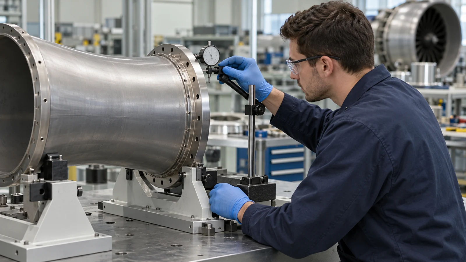
Use a controlled mating fixture or representative hardware for a fit check. Verify that the fasteners can be installed and that the seal interfaces as intended. A fit check cannot establish leak performance unless the approved method includes a defined leakage test.
For first article, record material traceability, joining or forming process records, finish state, dimensions, and approved deviations. If a leak or pressure test is required, the system authority defines the procedure and acceptance criteria. Keep component dimensional results separate from system-level test conclusions.
Prepare the release package
- Controlled duct and mating interface models, drawings, and revision.
- Approved material, heat treatment, joining, finish, and seal references.
- Functional datums, sealing-surface requirements, bolt pattern, and access envelope.
- Inspection method and support condition for the completed assembly.
- Required traceability, first-article records, and system-level verification references.
- Quantity, prototype or production status, cleanliness, and packaging needs.
An aircraft bleed-air duct flange is ready for manufacture when its sealing interface, mating structure, materials, process sequence, and acceptance evidence are defined together. That clarity helps avoid a flange that is dimensionally plausible but difficult to seal, install, or verify in the final duct route.

