


A spacecraft thruster bracket connects a propulsion component to a spacecraft structure while preserving its intended location and load path. The bracket may look like a compact support, yet its mounting faces, fastener pattern, local stiffness, clearance envelope, and thermal surroundings all influence the assembly. A manufacturing review should begin with those interfaces, not with a search for the lightest-looking shape.
Thruster installations vary widely. This article does not assume a particular propulsion type, temperature, vibration environment, or qualification requirement. The design authority defines those inputs. The goal here is to help engineers and buyers translate the released interface into a manufacturable prototype or production part without claiming system performance from geometry alone.
Trace the load path before shaping the bracket
Map how force moves from the thruster interface through the bracket and into the spacecraft structure. Identify the primary attachment face, secondary support, bolt pattern, and any feature that controls orientation. If the bracket carries a cantilevered assembly, the root transition and mounting plane may be more important than the outer contour. If two brackets support one unit, their relative position can be a system-level interface requirement.
Request the load cases, boundary conditions, and allowable deflection from the responsible engineering team. Manufacturing should not guess at those values or convert them into an arbitrary tolerance. The bracket drawing should translate the analysis into controlled surfaces and feature relationships, while the analysis remains the authority for the structural requirement.
Look for geometry that interrupts the load path: sharp internal corners, thin tabs around fasteners, abrupt wall transitions, or cutouts near a loaded root. These may be valid in the final design, but they deserve an engineering review before process selection. A prototype can help expose packaging and assembly conflicts; it cannot replace structural analysis or qualification testing.
Make mounting interfaces explicit
Define how the thruster body locates on the bracket. Is it positioned by a flat face, a pilot diameter, dowels, a shoulder, or a fastener pattern? A bolt pattern alone may not center the part reliably. The drawing should state the locating scheme and identify datum features that relate the thruster mount to the spacecraft-side attachment.
Check tool access to fasteners and installation sequence. A bracket can be machinable as an isolated part but impossible to install after adjacent equipment is in place. Show the tool approach, cable or tube clearances, and any keep-out around the propulsion assembly. If a spacer, insert, or isolation layer is part of the assembly, include its thickness and tolerance in the interface stack.
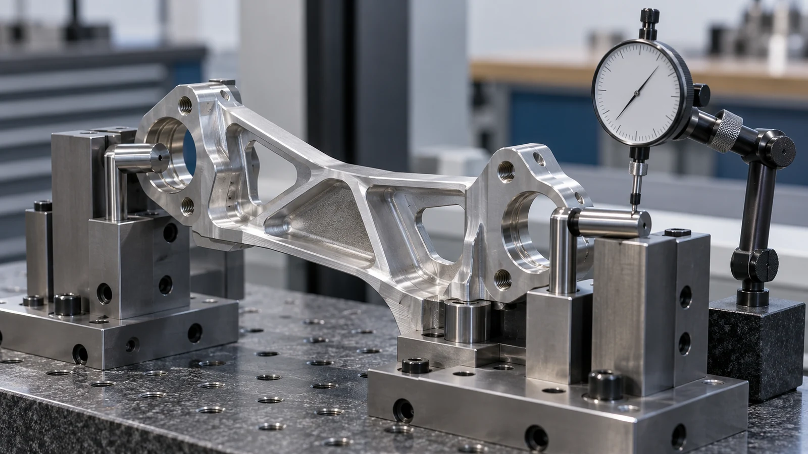
For parts that attach through several faces, avoid independent dimensions that do not close on a common datum. Position the critical interfaces in one coordinate scheme and specify which orientation controls inspection. The aerospace design-for-machining guide can help identify access and datum issues during the design review.
Remove mass without hiding risk
Weight reduction often motivates pockets, ribs, and topology-inspired shapes. Each cutout, however, changes stiffness, vibration response, local stress, tool access, chip evacuation, and inspection reach. A thinner web may save mass while becoming more susceptible to distortion during machining or to damage during handling. Ask whether every pocket has a structural purpose and whether the remaining wall can be measured and supported.
For a machined bracket, internal radii should reflect tool accessibility and the strength analysis. Tight corners can require small tools and long cycle times, while overly generous radii may interfere with a mating part. Add reliefs where they improve tool access without compromising the attachment surface. Keep critical pads large enough to clamp and inspect, or define sacrificial stock that is removed in a controlled final operation.
Additive manufacturing can create complex internal or lattice-like geometry, but it changes the process and verification questions. Build orientation, support removal, material condition, finish machining, and inspection access need to be addressed. It is not inherently lighter or more reliable for every bracket. Compare it with machining, sheet fabrication, or a hybrid approach using the actual geometry and quantity.
Choose the process after the geometry is stable
CNC milling is often a practical route for early bracket prototypes because mounting faces, bores, and pockets can be changed without dedicated tooling. Turning may suit a rotational interface or boss, while sheet-metal fabrication can work for a formed support if the load path and stiffness permit it. A hybrid assembly can use a machined interface block joined to formed members, but then joint design and tolerance stack become central.
Machining from billet can leave substantial scrap when the bracket is a thin, ribbed shape. The quote should account for stock size, fixture complexity, cutting access, finishing, and inspection. For a one-off prototype, design changes may justify this route. For repeated quantities, the team can compare alternate stock forms or construction after the interface has stabilized.
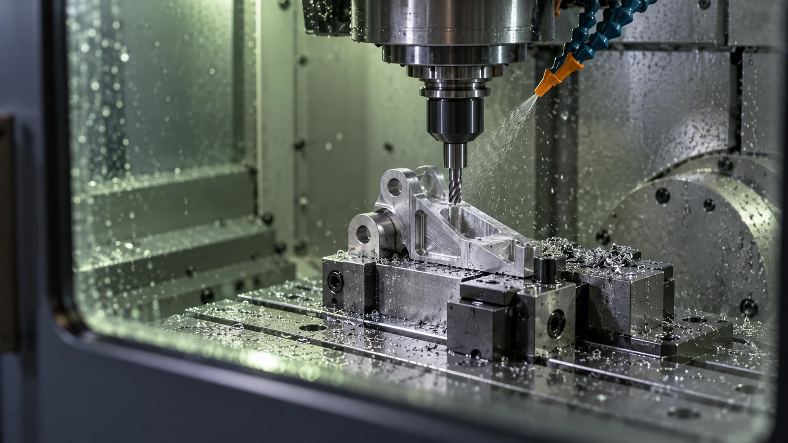
Use the aerospace manufacturing process guide to organize that comparison. Keep the final choice tied to the drawing revision, approved material, and intended verification. If a process changes the material condition or introduces a special process, it must be reviewed through the program’s controls.
Account for temperature and adjacent hardware
A propulsion component may operate near hot surfaces, lines, sensors, or thermal barriers. The bracket’s local temperature and heat path can differ from the surrounding spacecraft structure. Ask for the thermal envelope, contact assumptions, insulation or shield interfaces, and limits on coatings or lubricants. Do not infer temperature capability from a generic alloy name.
Material selection should balance stiffness, mass, thermal behavior, machinability, corrosion compatibility, and fastener interaction. Aluminum, titanium, stainless steel, or other materials may appear in different designs, but only the approved grade and condition can be quoted as conforming. If dissimilar materials meet at a joint, confirm the design’s galvanic and thermal-expansion controls.
Die aerospace materials overview can support early comparison, but the mission-specific analysis and drawing govern. Surface treatment also needs review: a coating may affect grounding, heat transfer, dimensions, or cleanliness at the interface.
Check the features that locate the thruster
Prioritize the thruster locating face, pilot or bore, fastener pattern, bracket-to-spacecraft interface, and any defined orientation feature. Inspection reports should reference the drawing revision and show measurements relative to the controlling datums. If two supports form one mounting set, consider a common fixture or assembly check so their relationship is verified rather than inferred from two separate reports.
Fit checks can reveal interference, tool-access issues, and fastener reach. They do not establish vibration survival, thermal capability, propulsion performance, or flight acceptance. State what the prototype is meant to prove and record any deviations from the released definition. If load testing is required, it belongs to the approved test plan with its own equipment, boundary conditions, and acceptance criteria.
Include material traceability, finish records, and inspection results as required by the program. The aerospace quality and inspection guide can help buyers define a practical evidence package without implying that a particular certification or approval exists.
For the wider spacecraft development context, see the site’s aviation and aerospace prototyping page, while keeping bracket-specific load and acceptance requirements on the controlled drawing.
Frequently asked questions
Is a thruster bracket usually a CNC part?
It may be machined, formed, additively manufactured, or built as a hybrid assembly. Geometry, loads, quantity, material, and inspection requirements determine the route.
Can topology optimization define the final design?
It can inform a design, but the responsible engineer must validate load assumptions, interfaces, manufacturing constraints, and verification. A generated shape is not automatically a released part.
Which dimensions are most important?
Start with the thruster locating interface, spacecraft attachment datums, orientation, and clearances. The drawing should tie these features to a common reference scheme.
Does a successful fit check qualify the bracket?
No. Fit confirms selected assembly questions. Structural, thermal, vibration, and program acceptance require their own approved analyses and tests.

