


A spacecraft separation ring forms a structural interface between two assemblies that must remain joined through launch and separate when commanded. Its success depends on more than the ring’s nominal diameter. The interface has to transfer the defined loads, mate with the adjoining structures, preserve the release system’s geometry, and meet the assembly and inspection requirements established by the program.
Because separation hardware is mission-critical, the design authority owns the release mechanism and safety requirements. A manufacturing partner should work from the controlled interface drawing and acceptance plan, not infer release performance from a CAD model. This article focuses on the mechanical ring and its manufacturing definition: the dimensions, datums, access, materials, and evidence that help prevent fit and alignment surprises.
Contents
- Define the separation plane and mating interfaces
- Map how the ring transfers load
- Control circular geometry in the assembled state
- Protect the release mechanism envelope
- Plan material removal and finishing
- Build a measurable acceptance plan
- Close the interface before procurement
Define the separation plane and mating interfaces
Start with the two structures that the ring connects. Identify the reference plane, locating features, bolt pattern, contact lands, and any interfaces to clamp bands, springs, or release hardware. The ring drawing should state which surfaces locate the assembly and which features provide clearance. If a separate adapter or shim is part of the interface, include it in the configuration baseline.
Clarify whether the ring is a structural member, a locating feature, a release-system housing, or a combination. Each function can impose different requirements on face flatness, radial runout, stiffness, and access. Avoid using one broad tolerance to represent all functions when the engineering intent can be expressed through specific characteristics.
Design reviews should include the deployment or separation authority, structural engineering, integration, manufacturing, and quality. Jucheng’s aerospace prototyping and manufacturing page is a general reference for low-volume hardware discussions; the mission-specific interface-control document remains the controlling definition.
Map how the ring transfers load
The ring may distribute loads around a circumference, but the actual load path depends on the attachment pattern, contact surfaces, adjacent structure, and mechanism design. The structural team should identify the governing launch and handling conditions, local stress limits, and required margins. Manufacturing needs the resulting controlled dimensions and inspection requirements.
Examine local features such as bolt holes, pockets, reliefs, interrupted contact lands, and thin flanges. These can create local flexibility or uneven bearing if their geometry is not coordinated with the mating structure. A continuous-looking ring does not guarantee uniform contact after assembly.
Also consider fastener preload and sequence as defined by the program. Uneven tightening can distort a ring or alter the contact at the separation plane. Do not put an invented torque or sequence on the component drawing; reference the approved assembly procedure and make sure the design allows the specified tools to reach the fasteners.
Control circular geometry in the assembled state
Large annular parts can be sensitive to workholding, stock removal, and temperature during measurement. A ring may meet its dimensions in a constrained setup and move when unclamped. Specify whether circularity, flatness, or runout requirements apply in a defined support condition or in the free state.

Use a datum scheme that relates the ring’s functional faces and locating diameter to the adjoining structure. If a clamp-band interface or release feature depends on a continuous radial profile, identify the controlling surface and how it is measured. Avoid relying on a collection of local dimensions that do not establish the ring’s overall orientation.
For assembly fit, a representative mating fixture can verify the interface, but the fixture must be controlled and traceable. A fit check answers whether the parts mate in that configuration; it does not establish structural margin or separation performance. Keep those verification objectives distinct.
Protect the release mechanism envelope
Release systems may include clamp bands, separation nuts, springs, connectors, or other mission-specific hardware. Their envelopes and clearances must come from the responsible mechanism design. The ring should provide the required mounting and access surfaces without obstructing moving components or changing the release path.
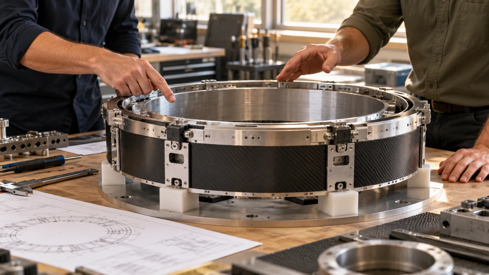
Check access for installation, inspection, and removal. A connector or fastener that is visible in the model may still be inaccessible to a tool once adjacent structures are installed. Consider cable routing and any permitted service loops around the ring. If harnesses cross a separation plane, the system design must define how they are managed; do not assume a manufacturing feature can resolve that hazard.
Manufacturing should preserve the controlled interface while avoiding burrs, sharp edges, and debris in mechanism areas. Specify edge treatments in a way that protects function but does not remove material from a critical contact land or alter a release-system clearance.
Plan material removal and finishing
Large ring parts may be turned, milled, or produced through a combination of processes depending on diameter, cross-section, quantity, and required interfaces. CNC machining can provide controlled annular faces and bolt patterns, but setup strategy matters. If the part is flipped between operations, datum transfer can affect the relationship between opposite faces.
Plan roughing and finishing so that distortion is managed and critical faces are completed in a stable condition. The exact sequence depends on stock, alloy, geometry, and the program’s approved material condition; do not assume stress-relief treatment unless it is specified and qualified for the component.
Surface treatment can change dimensions, friction, electrical bonding, or contact behavior. Define what surfaces receive treatment and what must be masked. For a precision annular interface, evaluate the post-finish dimension and inspection state. The CNC machining service can be assessed against the released ring geometry, material, finish, and inspection plan.
Build a measurable acceptance plan
Identify the characteristics that control assembly fit and structural function: annular face relationships, locating diameter, bolt pattern, local thickness, and release-system attachment features. Select measurement methods appropriate to size and tolerance. A large ring may require a coordinate measurement setup, precision fixture, or other validated method; the plan should state the datums and support condition.
For first article, record material traceability, revision, finish state, measurement setup, and actual results for critical characteristics. If a deviation is proposed, the responsible design authority determines its effect on the approved configuration. A shop-level concession should not silently change the separation interface.
Verification should distinguish dimensional acceptance from mechanism qualification and system-level separation tests. A ring inspection report proves only the measured features listed in that report. It does not establish a successful release event or vehicle-level performance.
Close the interface before procurement
- Controlled model, ring drawing, mating-part revisions, and interface-control reference.
- Material, condition, finish, masking, cleanliness, and traceability requirements.
- Functional datums, annular geometry, bolt pattern, and support condition for inspection.
- Release hardware keep-outs, tool access, and assembly configuration.
- Critical characteristics, first-article records, and deviation approval path.
A spacecraft separation ring is ready to quote when the interface, release-system envelope, material and finish, and acceptance evidence are defined. That clarity keeps manufacturing focused on a measurable structural component while preserving the design authority’s responsibility for the separation mechanism and mission verification.

