


Aerospace cold plate design is the engineering of a liquid-cooled mounting plate that transfers heat from avionics or power electronics into circulating coolant while preserving mechanical, thermal and service interfaces. The difficult decisions are not limited to channel shape: heat-source contact, pressure boundary, mounting flatness, connection access, mass and inspection all interact. For the wider industry context, see our aerospace prototyping and parts manufacturing overview.
A cold plate is not a complete cooling system by itself. It is one element in a heat path that may include the component interface, thermal interface material, coolant loop, pump, heat exchanger and control hardware. A plate that looks efficient in CAD can still be difficult to seal, clean, mount or inspect. Design review must connect thermal requirements to the part’s production and service conditions.
Contents
- Start with the heat path, not the channel sketch
- Compare architectures by their failure and inspection points
- Lay out channels around contact, flow and access
- Choose material with interfaces and joining in mind
- Translate the design into a manufacturable part
- Make verification part of the drawing package
- Frequently asked questions
Start with the heat path, not the channel sketch
The cold plate removes heat from defined contact regions. Component footprint, heat-source location, contact pressure and interface material are therefore early inputs, not details to add after the flow path is complete. A heat source near a mounting edge can create a different spreading problem from several evenly spaced modules, even when total heat is similar.
Begin with thermal boundary conditions from the system team: heat dissipation by device, allowable temperature at the mounting interface, coolant identity, inlet condition and expected operating cases. If these inputs are preliminary, label them as assumptions and identify which calculations must be repeated when they change. Do not hide uncertainty inside an arbitrary channel dimension.
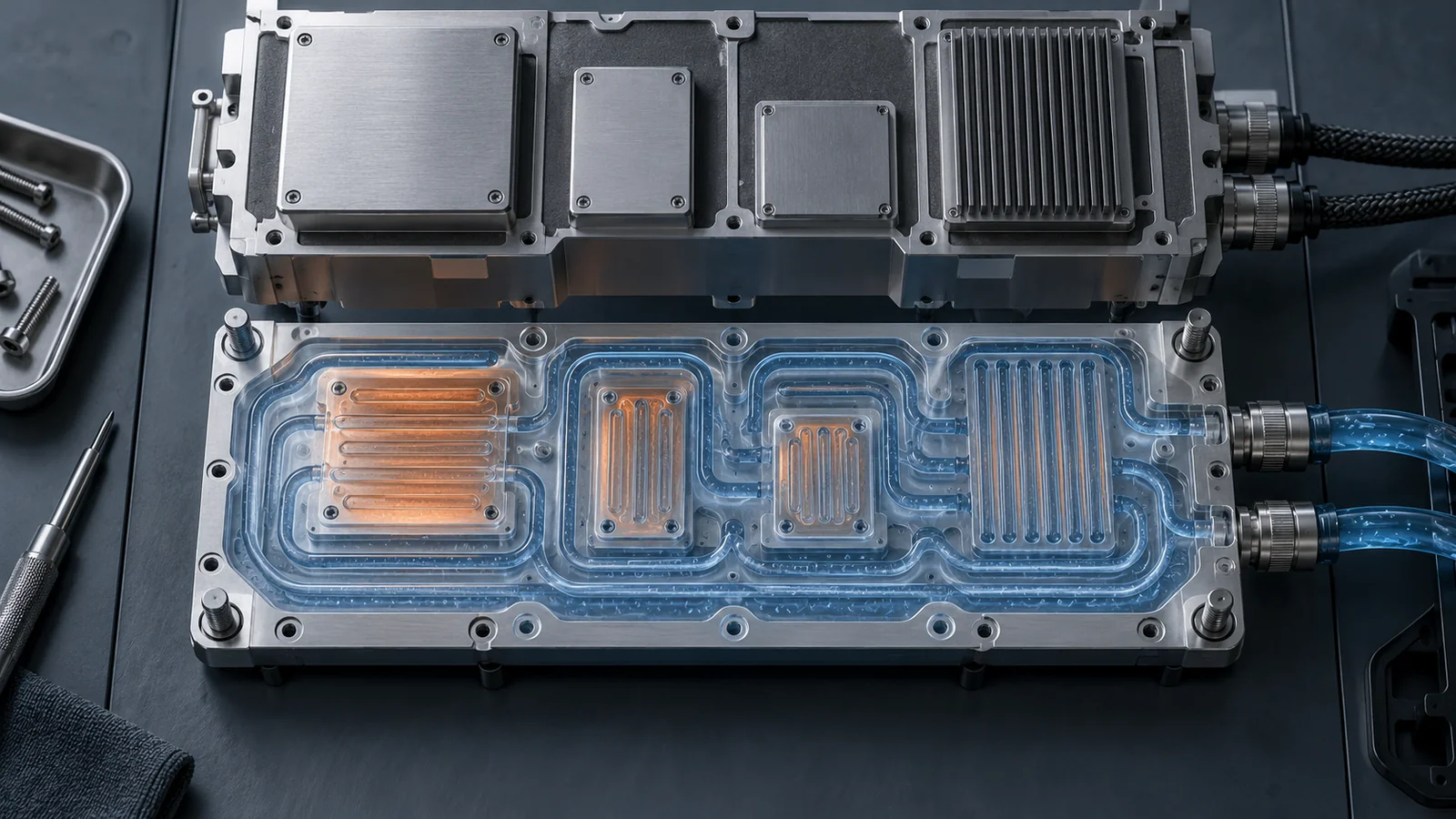
Thermal performance is coupled to pressure drop and pump capacity. A narrow winding passage may increase wetted area but impose more flow resistance; a broad passage may be easier to machine and clean yet distribute heat differently. The right balance depends on the system model, not a universal best pattern. SAE’s AIR1277B guidance on cooling military avionics treats air- and liquid-cooling methods within a broader equipment thermal-design context.
The useful design question is whether the plate can maintain the required component interface while the coolant loop stays within its allowed operating range. That question is more actionable than asking whether a channel looks compact.
Compare architectures by their failure and inspection points
Architecture affects internal passage access, the number of sealing boundaries and what can be inspected after manufacture. A one-piece plate with drilled passages, a covered channel plate and a bonded or brazed stack can each be reasonable; the drawing and validation plan must make the selected route auditable.
| Architektur | Potential advantage | Design question |
|---|---|---|
| Machined block | Integral body and accessible port features | Can intersecting drill paths be deburred and cleaned? |
| Open channel with cover | Channels can be formed or machined before closure | How will the joint be sealed, joined and inspected? |
| Bonded or brazed stack | Complex flow distribution can fit a compact envelope | Are joining, distortion, cleanliness and proof criteria defined? |
| Tube or insert-based plate | Separates coolant conduit from some body features | Can the interface maintain contact and support the tube? |
This is a selection aid, not a qualification table. Material, joining and acceptance requirements must follow the approved design authority and program documentation. A simpler prototype architecture may confirm fit and thermal assumptions, while production selection must also consider repeatability, inspection, service access and the effort required to verify hidden features.
Map failure paths for every concept: leakage at a port or joint, restricted flow, poor device contact, mounting-face distortion, corrosion incompatibility or contamination inside the passage. A useful review says both how failure could occur and how it would be detected before integration.
Lay out channels around contact, flow and access
Route channels around the heat-source map while preserving material for pressure boundaries and fasteners. Keep-outs around ports, edge distances, mounting bosses and seal grooves matter when a passage bends near a face. A thermally attractive route that intersects a fastener bore or weakens a sealing land is not viable.
Flow distribution needs a separate review. Parallel branches offer short paths but may not divide flow evenly if their hydraulic resistance differs. A serpentine route simplifies topology but can create a temperature gradient along its length. Multi-pass layouts can solve packaging constraints while increasing the importance of pressure-drop analysis and cleaning access. These are system tradeoffs; dimensions cannot be prescribed without heat-load and coolant data.
Port location affects installation as well as fluid flow. A fitting needs wrench clearance, the connected line needs a workable bend and support strategy, and the port thread or sealing form must match the fluid-line specification. Avoid a port location where installation torque could distort a thin cover or where a line blocks removal of nearby electronics.
Cross-drilled passages may leave burrs at intersections, and the internal junction can be hard to reach. Specify deburring access or an agreed method, then define how cleanliness is demonstrated. If direct inspection is impossible, validation should address the hidden geometry rather than assume it is clear.
Choose material with interfaces and joining in mind
Selection should weigh thermal conductivity with strength, corrosion compatibility, joining route, mass, machinability and contact interfaces. Aluminum alloys are common in lightweight thermal hardware, but the grade and temper must come from program requirements; no one alloy is automatically suitable for every coolant, joining method and environment.
Review galvanic couples, coolant chemistry and surface treatment. A coating can protect a surface but may change contact resistance, dimensions or seal behavior. Bonding or brazing may affect distortion and material condition. With a plate machined from stock, channel depth and wall thickness influence stiffness, tool access and finishing sequence.
The thermal contact face is a functional interface. Define datums relative to mounting features and coolant ports, then identify which surfaces carry flatness, finish or positional requirements. Those requirements should reflect the device interface and assembly method rather than values copied from an unrelated part.
Material records should identify specification, grade, temper or condition, lot traceability and any program evidence. Our aerospace materials guide provides parent context for material choices; final selection belongs to the design authority.
Translate the design into a manufacturable part
Invite manufacturing review before freezing the channel pattern. Ask whether passages can be drilled or milled with available access, whether tools can reach their depth, and whether the part can be held without distorting its contact face. Deep or angled passages, thin covers and closely spaced ports may drive the operation sequence more than the outside shape.
Plan datums from functional interfaces outward. The mounting face may establish the first setup; ports and channel features then need a consistent relationship to that reference. If a cover is joined after machining, plan for joint distortion and decide whether a finish operation is needed after joining. If seals are used, state how groove geometry and surface condition will be verified.
For low-volume prototypes, a thermal-fit mock-up may be separated from a pressure-bearing validation article, but the distinction must be controlled. A nonfunctional mock-up must not be represented as pressure qualified. Production-intent samples should use the intended material, joining route and inspection path whenever those variables affect performance.
For CNC-machined ports, faces or complex features, review the part against our aerospace CNC machining overview. Supply the drawing, 3D model, material condition, critical characteristics and expected quantity for manufacturability review.
Make verification part of the drawing package
Connect every requirement to a method and record. Dimensions may be checked by measurement; a hidden passage may need a flow, pressure or leak test; thermal behavior may require a defined test setup with controlled boundary conditions. Agree on the method before build so the design does not depend on evidence that cannot be collected afterward.
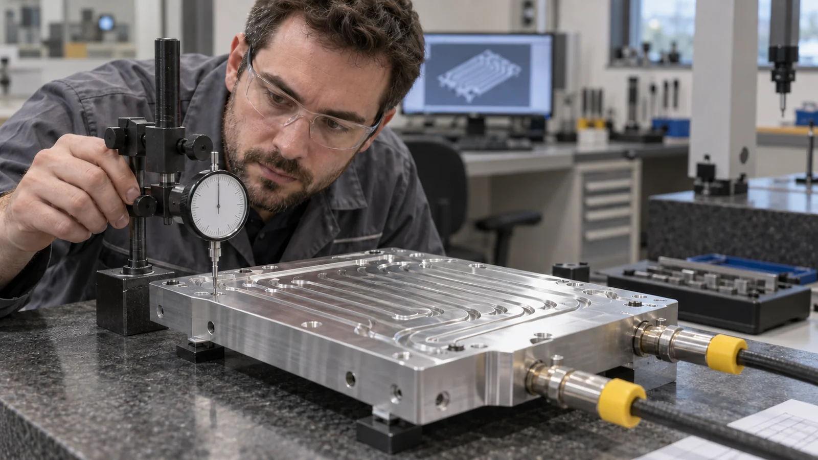
- Define pressure and leak-test boundaries, fluid, duration, criteria and safe setup.
- Record flow direction, inlet condition and configuration when flow performance matters.
- Identify datums and critical contact and mounting dimensions.
- Specify internal cleanliness and how passages are flushed, dried or inspected.
- Retain material and joining records when they affect released configuration.
Test values must come from the controlling specification or approved engineering plan. Do not replace program requirements with a generic proof pressure or thermal target. A traceable report should identify part revision and configuration so evidence stays tied to the evaluated hardware.
The best cold plate is not simply the one with the most elaborate channel. It is the architecture whose thermal path, sealing interfaces, manufacturability and verification evidence agree with the system requirement.
Frequently asked questions
Is an aerospace cold plate the same as a heat exchanger?
Not exactly. A cold plate transfers heat from mounted equipment into coolant. A separate heat exchanger may then transfer that heat from coolant to another fluid or environment. They can be parts of one loop but have different interfaces and design responsibilities.
Should channels be machined or bonded?
Choose according to thermal analysis, pressure boundary, passage access, material and joining constraints, inspection, serviceability and volume. Channel appearance alone cannot determine the better route.
What should accompany a cold-plate manufacturing inquiry?
Provide the drawing and model, heat-source map, interface requirements, coolant and operating envelope, port definition, material condition, quantity, joining requirements and proposed verification criteria. Mark assumptions and open items clearly.

