


A hydraulic manifold can look like a compact block of metal, yet its internal route determines whether a system is straightforward to assemble, inspect and maintain. For aerospace hardware, the drawing must communicate more than the outside envelope: it must define ports, passage intersections, sealing geometry, material condition and the evidence needed to release the part.
This guide focuses on design-for-manufacture questions for custom aerospace hydraulic manifolds. It is not a repair procedure or a substitute for the applicable system specification. The goal is to help engineering and procurement teams catch avoidable risks before a prototype or production order reaches the machine shop.
Start with the fluid route, not the outside shape
Begin by mapping each inlet, outlet, branch and plugged access point. A simple route sketch can expose a problem that is difficult to see in an isometric view: two passages may intersect too close to a port, a tool may not reach a deep feature, or a plug may obstruct a later assembly step. Mark the functional path first, then shape the block around it.
For each passage, identify its purpose, nominal size, direction and relationship to the mating component. Distinguish a required flow path from a drilling access path. The latter may be closed by a plug, but it still affects wall thickness, chip evacuation and inspection. A clear route map also helps suppliers identify which features need special attention instead of treating every hole as an equivalent operation.
When packaging is tight, review whether a passage can be routed with fewer turns or fewer intersecting bores. This is not a blanket instruction to maximize bore size: pressure, flow, cleanliness, structural margins and the governing design authority control the final dimensions. It is a prompt to identify the design tradeoffs before releasing a production drawing.
It is useful to annotate a preliminary model with a route identifier for every branch. The identifier need not become a permanent drawing requirement, but it gives design, manufacturing and inspection teams a shared way to discuss the same internal feature. It also makes change review easier: if a port moves, the team can trace which branches, walls and inspection steps are affected rather than reviewing the outside shape alone.
Make port interfaces unambiguous
Port definition is often where a seemingly complete model becomes an incomplete manufacturing package. Specify the connection standard and the exact thread form, size, class or fit where applicable. A callout that says only “threaded port” leaves room for incompatible assumptions. Also identify the sealing method: a straight thread with a separate seal, a tapered thread, a face seal, or another defined interface are not interchangeable descriptions.
Dimension the features that establish assembly: thread depth, counterbore or spotface, chamfer, sealing-land width, and the relationship between the port axis and nearby faces. If a fitting must clock to a certain direction, define that requirement in the assembly or drawing rather than relying on the appearance of a 3D model. Avoid adding cosmetic dimensions that conflict with the controlled CAD definition.
A useful review asks what the machinist, inspector and assembler each need to know. The machinist needs a manufacturable feature definition; inspection needs measurable acceptance criteria; assembly needs to know how the fitting seats and seals. If one group must infer a critical interface from a rendered model, the package is not ready.
Port numbering and orientation deserve the same care as dimensions. When a block has several similar connections, a labeled view or a controlled port table can prevent a correct feature from being connected to the wrong circuit during integration. Keep labels consistent across the model, drawing, bill of materials and assembly documentation. Do not use the drawing to imply a fitting or seal is included if the purchase scope does not include it.
Treat cross-drilled passages as a design system
Intersecting bores create access, but they also create burrs and local geometry that are hidden after assembly. On the drawing, identify each intersection and decide how it will be deburred, cleaned and verified. “Break sharp edges” may be adequate for an ordinary exterior edge but is too vague when a burr could remain in a fluid path or when access is restricted.
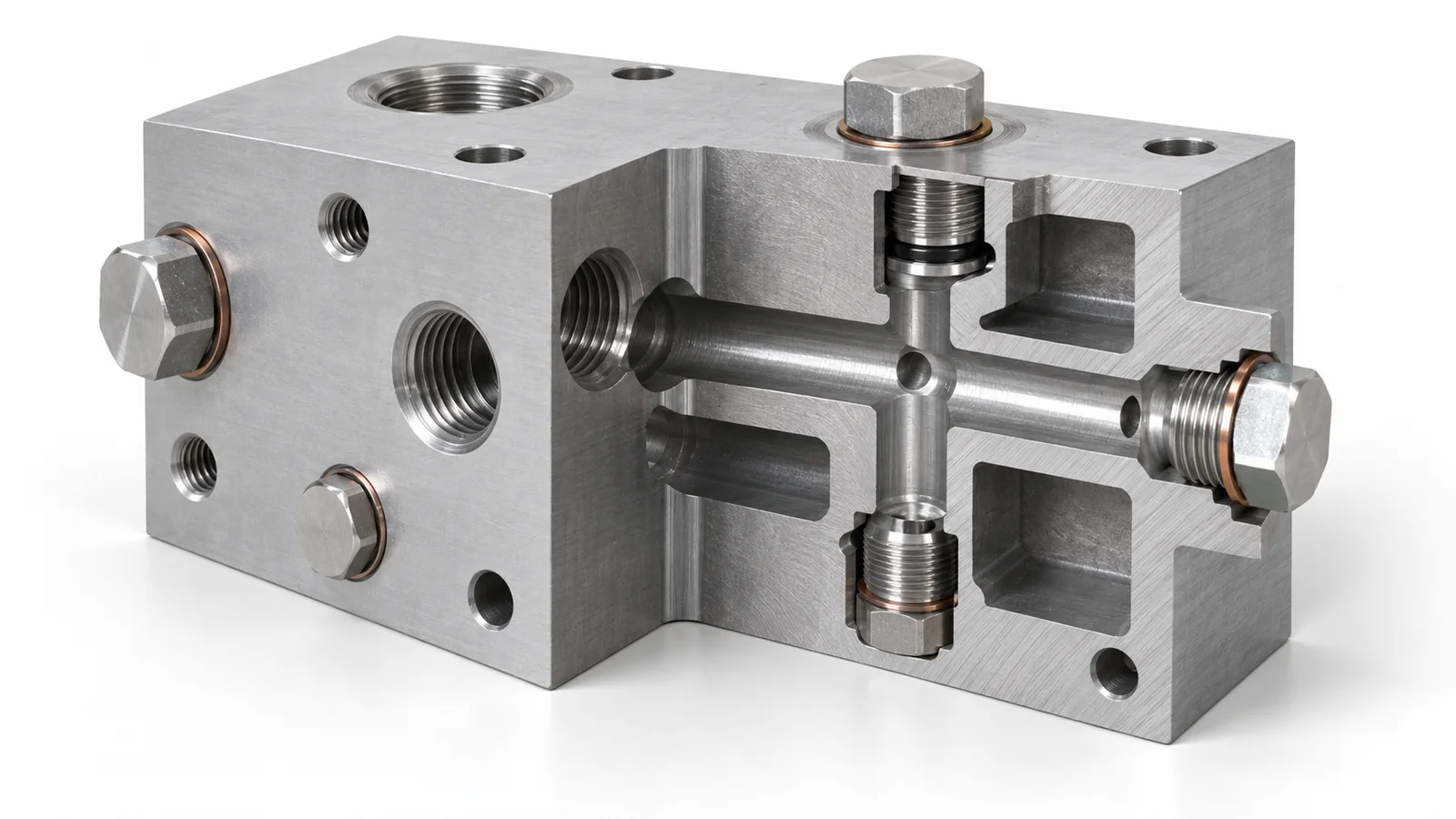
Choose plug locations and styles with service access and inspection in mind. A closure must not conceal a feature that still needs verification, and its installation should not damage the surrounding sealing surface. For a complex manifold, a passage table can connect each route to its drilling direction, access opening, closure and inspection method. This makes design reviews more concrete than relying on multiple disconnected section views.
Where a passage cannot be inspected directly, agree on a practical verification method before machining. Depending on the part and governing requirements, that may involve visual access, a defined cleanliness process, dimensional checks, or a documented test. Do not assume a particular test is required or sufficient without the contract and engineering authority defining the acceptance criteria.
Tool access affects more than whether a drill can reach the feature. The selected tool length, workholding orientation, breakthrough location and chip evacuation path all influence the manufacturing sequence. A passage that appears simple in CAD may require several setups or create a fragile breakout at an adjacent face. Ask the supplier to identify these risks during quotation, while keeping final geometry and acceptance decisions with the design authority.
Protect sealing faces and thin walls
Flatness, finish, perpendicularity and surface damage matter where a fitting or cover seals. State the actual functional controls needed at the interface, and make clear which datum scheme governs them. Tightening every surface finish or tolerance without a functional reason can increase cost while obscuring the few characteristics that truly determine fit and sealing.
Review minimum wall sections between intersecting passages, ports and the outside envelope. The nominal CAD wall is not always the final wall after tolerances, spotfaces, edge breaks and tool runout are considered. A section view through the most crowded region can reveal a fragile web or a breakthrough risk earlier than a general exterior review.
Material choice and condition must match the approved design basis. The manufacturing supplier should not substitute an alloy, temper, coating or heat-treatment condition simply because it machines more easily. If a surface treatment is specified, account for its effect on critical dimensions and sealing geometry, and define which dimensions are measured before or after treatment.
Also identify surfaces that must remain free of machining damage during clamping and later operations. A finished sealing face can be scratched by an adjacent setup or distorted by an unsuitable clamping strategy. The process plan should protect those interfaces without adding unneeded cosmetic controls to unrelated faces.
Plan inspection around hidden features
Inspection planning should start from the characteristics that affect connection, sealing, flow routing and interchangeability. Identify critical dimensions and datums, then choose measurement methods that can actually reach them. External calipers cannot verify the condition of a deep cross-hole, and a general visual inspection cannot replace a defined acceptance method for a controlled port.

For a machined prototype, request a drawing-linked inspection record that identifies the part revision and the measured characteristics. If material traceability, special-process records or a cleanliness statement are required by the purchase order, spell them out before order placement. The relevant records depend on the customer’s quality system and contract; they should not be inferred from the word “aerospace.”
A first-article review can be especially useful when the route, tooling access or port interface is new. It provides a structured opportunity to compare the manufactured part with the released definition before repeating the process. That review is only meaningful when the drawing revision, material identification and inspection results are tied together.
When a feature is difficult to measure, define the evidence before cutting metal. A supplier may be able to propose a suitable method, but the customer must confirm that the method corresponds to the drawing requirement. This avoids the late discovery that the part is physically complete yet the required characteristic cannot be demonstrated with the agreed record.
Close the loop with a complete drawing package
Before requesting a quote, assemble the controlled 2D drawing, current 3D model, revision level, material and condition, surface-treatment requirements, inspection criteria, quantity and delivery assumptions. Add a passage map or section views when the internal route is not obvious. State whether the supplier is expected to quote machining only or also defined finishing and documentation steps.
For teams sourcing across the broader aerospace manufacturing process landscape, keeping the manifold’s functional requirements connected to the project’s material, machining and verification decisions helps prevent the part from being treated as an isolated block. The manufacturing route should follow the controlled design, not replace it.
A concise design-for-manufacture review can be organized around six questions:
- Can every required passage be machined and deburred through a defined access route?
- Are port standards, sealing methods and clocking requirements explicit?
- Are the minimum walls and sealing lands measurable and protected?
- Does the inspection plan address hidden or hard-to-reach features?
- Are material, treatment and documentation requirements tied to the revision?
- Does the quote scope identify what is included and what remains customer-controlled?
Answering those questions before release reduces interpretation risk. It also makes supplier feedback more useful: instead of a generic request to clarify, the team can discuss a specific port, intersection, datum or evidence requirement.
A supplier conversation is most productive when it happens against a stable revision. If design intent is still changing, flag the model as preliminary and separate budgetary feedback from a production quotation. Once released, keep revisions traceable so that a change to one passage does not leave earlier inspection instructions or procurement notes in circulation.
Frequently asked questions
Should every cross-drilled passage use a removable plug?
Not necessarily. The closure and access strategy depend on the approved design, pressure boundary, inspection needs and system requirements. The drawing should define the selected solution and its acceptance criteria rather than leaving the supplier to choose.
Can a supplier select a similar alloy if it is easier to machine?
No substitution should be assumed. Material grade, product form and condition must follow the released engineering definition and purchase requirements. Any proposed change needs formal customer or design-authority approval.
What should be included in a manifold RFQ?
Provide the controlled drawing and model, revision, material condition, quantity, required finishes, inspection and traceability needs, and the intended scope of supply. Identify questions that require supplier feedback before quotation.

