


Start With the Question the Part Must Answer
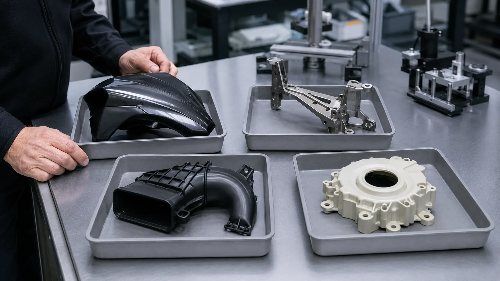
Process selection becomes clearer when the engineering question is stated first. A visual buck, a fit-check bracket, a functional duct, a lightweight cast housing, and a pilot-run molded cover may share the same CAD workflow but need different manufacturing routes.
| Part objective | Useful first routes | Decision to protect |
|---|---|---|
| Form and ergonomics | 3D printing, CNC, vacuum casting | Appearance, edge feel, revision speed |
| Fit and assembly | CNC, sheet metal, molded prototypes | Datums, interfaces, holes, fasteners |
| Short functional test | CNC, reinforced printing, RIM, casting | Material behavior and load direction |
| Small pilot quantity | Rapid tooling, molding, CNC, casting | Repeatability and inspection evidence |
This framing prevents a common mistake: choosing the lowest unit price before knowing whether the parts will support the required test.
Four Process Families That Cover Most Early Decisions
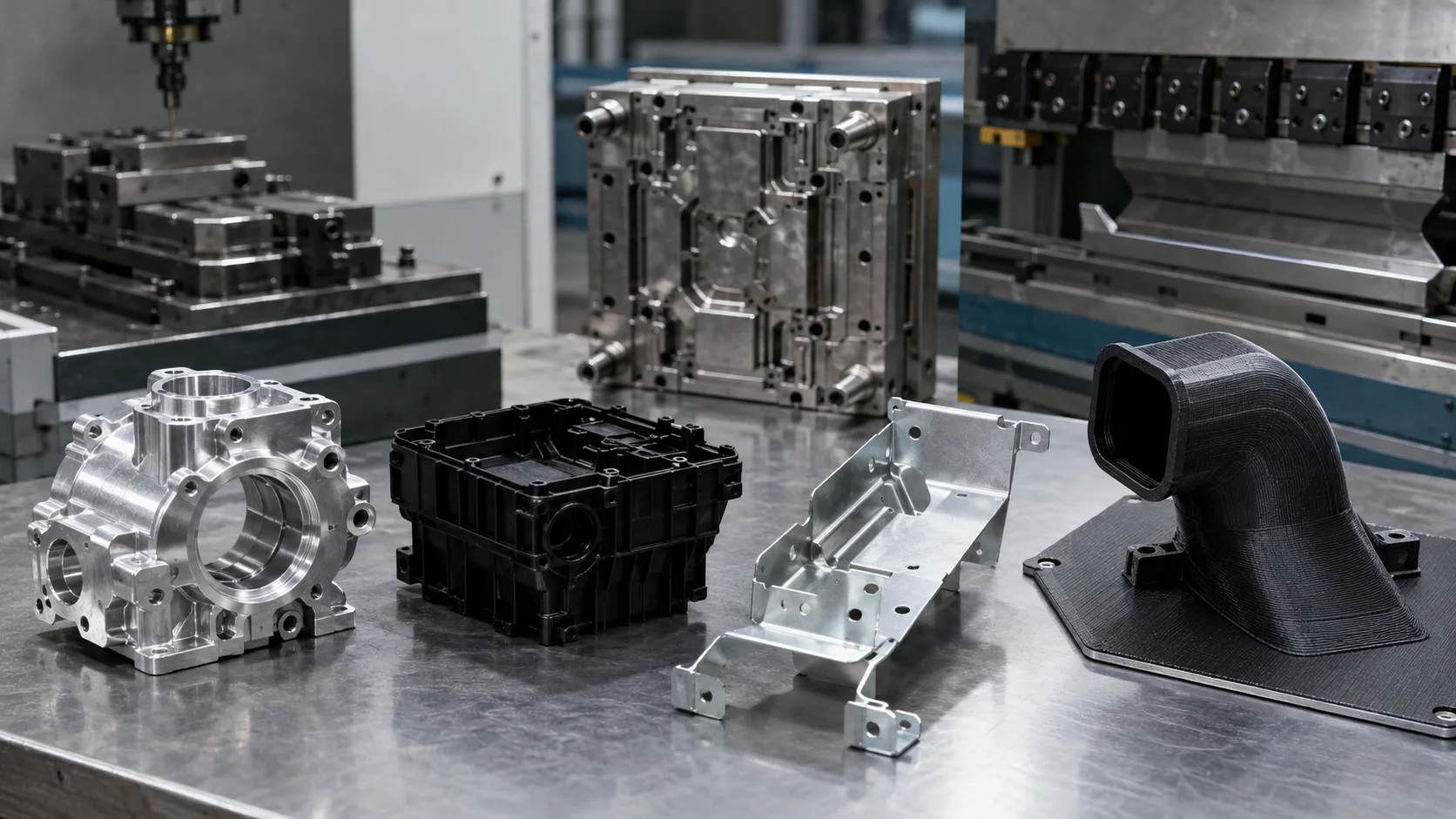
CNC-Bearbeitung
CNC-Bearbeitung is a strong starting point for accurate metal or plastic parts, datum-critical interfaces, and low quantities where tooling would add delay. It remains useful when the design is changing or a machined surface is part of the evaluation.
Spritzgießen
Spritzgießen becomes more attractive when geometry, material behavior, and quantity justify a mold. Draft, wall transitions, ribs, bosses, parting lines, and ejection should be reviewed before tool steel is committed.
Blechbearbeitung
Laser cutting, bending, joining, and finishing make Blechbearbeitung useful for brackets, enclosures, shields, structural covers, and assemblies that benefit from real gauge material.
3D-Druck
3D-Druck shortens the path to complex geometry and is often ideal for early reviews, ducts, ergonomic studies, and internal features that are difficult to machine. Orientation, anisotropy, support removal, and finishing determine whether it suits the test.
Die casting, vacuum casting, reaction injection molding, and rapid tooling can be added when part size, appearance, material behavior, or volume changes the balance.
A Process Decision Map for Automotive Programs
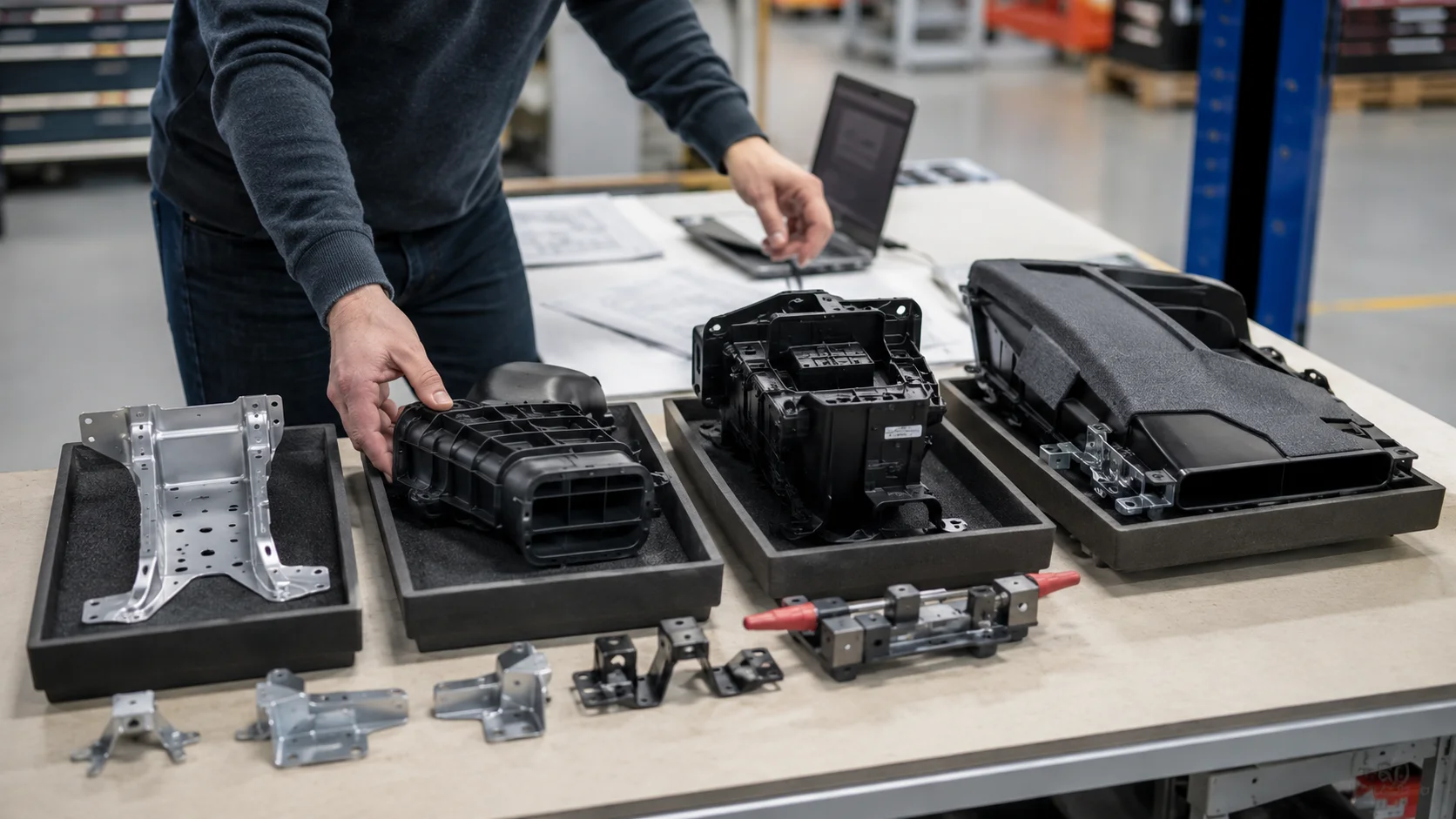
- Need a fast geometry check? Begin with a suitable print or machined prototype and keep the revision loop short.
- Need a real interface? Protect datums, holes, threads, sealing faces, and mounting features.
- Need molded behavior? Review draft, wall thickness, shrinkage, texture, and ejection assumptions.
- Need realistic cosmetic parts? Compare vacuum casting, finished printing, molded samples, or painted machined parts according to the review objective.
- Need a repeatable pilot? Compare tooling investment, tool life, material qualification, inspection, and change cost—not unit price alone.
A decision map keeps the engineering risk visible instead of hiding it behind a generic “best process” claim.
When Combining Processes Adds Value
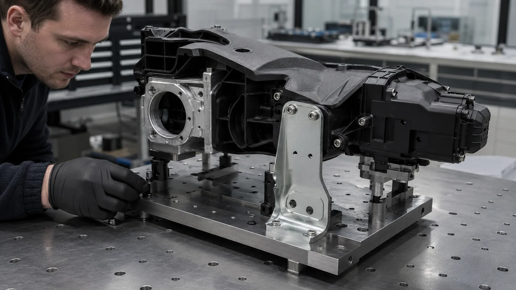
Many vehicle parts are best developed through a sequence. A printed master can support a cosmetic review, a machined insert can verify an interface, and a rapid tool can produce pilot pieces after the design stabilizes. A fabricated bracket may be combined with a printed cover to validate packaging before either route is finalized.
Every handoff should identify the CAD revision, material assumption, finish level, critical dimensions, and test purpose. Otherwise a later process may be judged against an earlier design intent.
Quality Planning Must Follow the Process
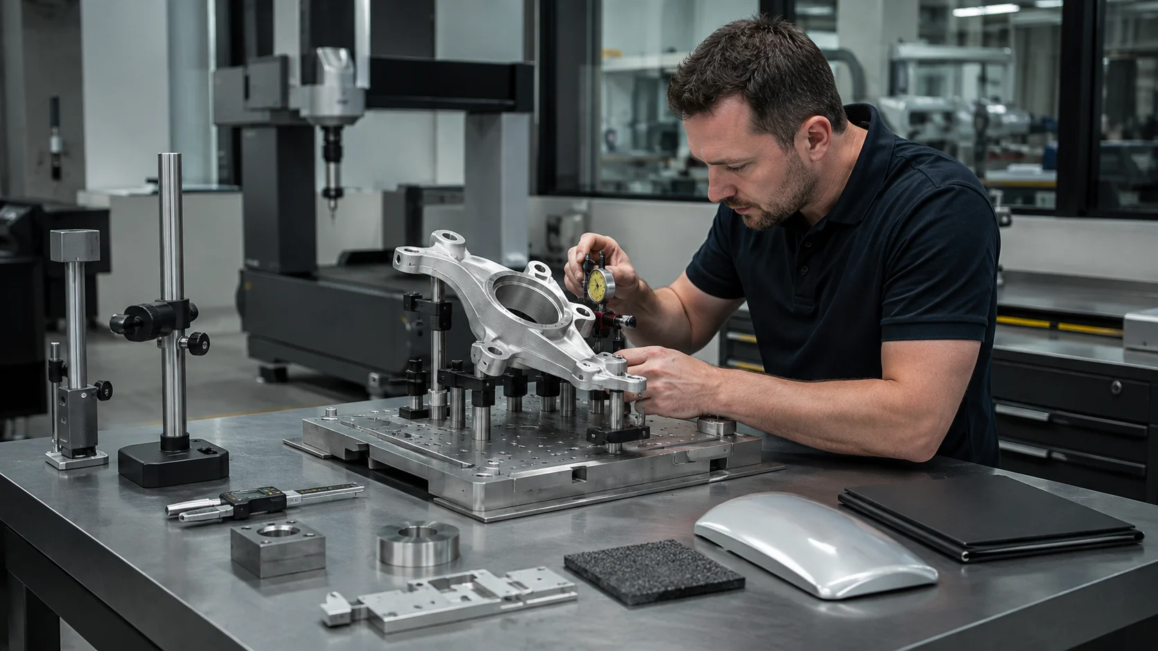
| Risiko | Control to define | Evidence to request |
|---|---|---|
| Interface mismatch | Datums and critical dimensions | Targeted report or assembly check |
| Material mismatch | Grade, condition, test environment | Material declaration and test notes |
| Cosmetic variation | Visible surfaces, texture, gloss, color | Approved sample and visual limits |
| Process drift | Revision, batch, inspection records | Traceable build documentation |
Do not claim production compliance from a prototype process unless the relevant material, process, inspection, and quality requirements have been verified for that build.
Prepare an RFQ That Can Be Decided
- Provide the current CAD model, drawing, revision, and quantity.
- Mark critical interfaces, visible surfaces, datums, and features that must remain uncoated.
- State the purpose: visual review, fit check, functional test, customer sample, or pilot build.
- Describe material, finish, joining, packaging, inspection, and test conditions.
- Ask for the recommended process and its main trade-off, not only a price.
This lets a manufacturing partner compare routes responsibly and explain effects on cost, timing, appearance, and evidence quality.
Häufig gestellte Fragen
Which process is best for an automotive prototype?
There is no single best process. Choose based on the test: printing for rapid geometry, CNC for accurate interfaces, sheet metal for formed assemblies, and molding or casting when material or appearance must be closer to production intent.
Should tooling be made for the first prototype?
Usually not if geometry or requirements are changing. Tooling becomes more defensible after key design reviews when expected quantity or molded behavior justifies the investment.
Can one supplier manage several processes?
A multi-process supplier can simplify revision control and handoffs, but each process still needs its own material, quality, and acceptance criteria.

