


A semiconductor gas manifold block can look like a compact metal part, yet its internal passages and external sealing interfaces determine whether the assembly routes process gas as intended. The design may include cross-drilled channels, plugged access bores, threaded ports, valve seats, mounting faces, and several distinct seal lands. A passage that is open in CAD can be partially obstructed by a burr; a clean-looking block can still leak if a sealing face is damaged or a plug interface is mismanaged.
The manufacturing challenge is therefore not simply to machine a port pattern. It is to preserve the drawing-defined flow path, sealing geometry, material identity, and cleaning requirements through a controlled sequence. This component-level view supports the main semiconductor equipment parts manufacturing topic while staying focused on gas-delivery blocks rather than the entire tool.
- Translate the flow schematic into machinable features
- Protect seal lands and port interfaces
- Sequence cross-drilling, plugging, and deburring
- Specify wetted material and surface condition
- Treat cleanliness as part of the process plan
- Inspect what the drawing and function require
- Prepare a gas manifold RFQ that can be reviewed
Translate the flow schematic into machinable features
Before release, reconcile the flow schematic, 3D model, and drawing. Identify each inlet, outlet, branch, dead-end, plug, and connection type. Then verify that the intended passages intersect where required and remain separated where isolation is required. A drawing should make it possible to distinguish a through-bore from a blind bore and show how a cross-drilled access port is closed after machining.
For a multi-channel block, color-coded CAD can help design review, but color is not manufacturing evidence. Use section views, centerlines, dimensions, and controlled notes to define the path. Check wall thickness between adjacent channels, distance from a port to an outer face, and whether a tool can reach the required depth. If a passage intersects at an angle, decide how the intersection will be inspected or cleaned rather than assuming it is automatically complete.
Flow performance depends on system design, gas properties, pressure, flow, and the equipment configuration. The part drawing may control geometry, but it should not imply a flow rate or process result unless the design authority supplies and verifies those requirements. The machining supplier can review the geometry and identify manufacturability risks; the system owner retains responsibility for process performance.
Protect seal lands and port interfaces
Port geometry should be tied to the specified fitting or sealing standard. A port thread, face seal, gasket land, or metal-to-metal interface each imposes different requirements on dimensions, surface finish, flatness, and edge condition. Avoid using a generic note such as “leak tight” without defining the connection, test method, acceptance threshold, and test configuration.
Seal faces should be protected through handling and finishing. A nick, embedded particle, or raised burr can create a leakage path even when the nominal dimensions are within limits. Specify whether these surfaces are masked, how the block is handled after machining, and which inspection method is appropriate. When a coating or electropolishing step is required, confirm its effect on the sealing geometry and any thread or groove dimensions.
Port orientation also matters at assembly. The connection needs wrench access, correct fitting alignment, and clearance from neighboring valves or panels. Include adjacent components in the model or provide an interface drawing. A block can satisfy its own drawing and still be impossible to assemble if the fitting envelope was never reviewed.
Sequence cross-drilling, plugging, and deburring
Cross-drilled passages require deliberate sequencing. The machinist needs to know which faces are accessible for drilling, which openings will be plugged, and which features serve as datums for later operations. Plug depth, thread engagement, sealant or weld requirements if any, and the final outer profile should be coordinated. A plug is a functional part of the flow boundary and should not be treated as an incidental closure.
Deburring internal intersections can be more difficult than deburring an exposed edge. Tool choice depends on passage size, intersection angle, material, and access. A process plan may combine mechanical tools, abrasive methods, flushing, and visual or borescope review, but the required method should be agreed with the customer and quality plan. No single generic operation proves that every internal edge is free of loose material.
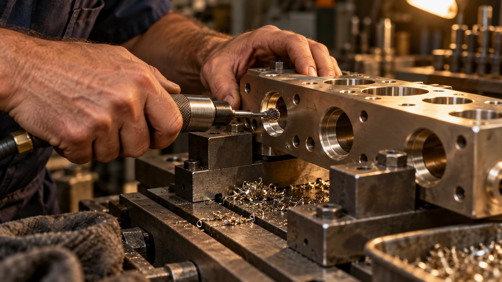
Machining sequence should preserve critical datums and sealing faces. Roughing internal geometry before final finishing may reduce the chance that later stock removal distorts a finished interface. If plugs are installed before a final operation, protect the block from chips and damage. The exact sequence depends on the design, so the supplier review should identify the critical order rather than promise a universal recipe.
Specify wetted material and surface condition
Material choice must match the gas chemistry, pressure and temperature range, cleaning method, and connection design defined by the process system. Stainless steel may be specified for particular wetted components; aluminum may be used in other equipment architectures. Corrosion resistance and machinability are only part of the decision. The material grade, product form, condition, traceability documents, and any restrictions on contamination must be explicit.
Surface requirements should distinguish a sealing face from an internal wetted passage and an external mounting face. A part may need machining marks controlled on one interface while other areas use a separate finishing process. Specify finish using a measurement method and location where required. Avoid assigning an unverified cleanliness class or roughness number just because it appears in a supplier brochure.
Jucheng’s stainless steel machining information und semiconductor equipment materials overview can help organize an initial discussion. The final material and surface specification must come from the gas-system design authority and account for the actual media and cleaning process.
Treat cleanliness as part of the process plan
Chips, cutting fluid residue, abrasive remnants, and handling debris can remain in intersecting passages long after the outside of a block has been wiped. Define the sequence for deburring, flushing, drying, inspection, and packaging. If the part has caps or protective plugs, specify when they are installed and how they are kept clean. Packaging should preserve the approved state during storage and transport.
Cleaning requirements should be measurable and relevant to the application. If particle, ionic, hydrocarbon, or other contamination limits are required, identify the method and acceptance criteria. If the project only needs a defined cleaning and protective packaging sequence, state that accurately. A phrase such as “semiconductor clean” alone can mean different things to different suppliers and inspectors.
The site’s semiconductor finishing, cleaning, and quality guide is the broader process context. For a specific manifold, link cleanliness evidence to the part revision and production lot, and ensure the packing method does not reintroduce contamination after final cleaning.
Inspect what the drawing and function require
Inspection can include port position, thread or groove dimensions, sealing-face geometry, datum relationships, wall thickness, plug condition, and the defined leak test. The plan should state which features are checked on the bare block and which are checked after finishing or plug installation. A leak-test report needs the test medium, setup, pressure or vacuum condition, duration, and acceptance rule defined by the customer.
Internal passage inspection may require a combination of drawing review, visual access, borescope, flushing evidence, or other agreed methods. Where direct measurement is impossible, the acceptance plan should explain how process control and verification are established. Do not claim that a dimensional report proves cleanliness or that a leak check proves every passage is free of burrs; each piece of evidence answers a different question.

Keep material records and drawing revisions with the inspection package. A port relocation, a changed plug, or a different finishing sequence can alter the process even if the block outline looks unchanged. Revision control prevents a previously approved sample from being treated as evidence for a new geometry.
Prepare a gas manifold RFQ that can be reviewed
Provide a 3D model, fully dimensioned drawing, flow schematic, material and condition, port and fitting specifications, finish and cleaning requirements, quantities, revision, and inspection plan. Mark the sealing faces, internal channels, plugs, and areas that must be protected. Identify whether the request covers a prototype, pilot batch, or repeat supply.
Ask for a manufacturability review of drill access, channel intersections, remaining wall sections, deburring access, plug installation, and test setup. If the gas chemistry or cleanliness limit is not yet approved, flag it as an open design input instead of asking a supplier to guess. The semiconductor precision machining overview provides a related process link, while the manifold drawing remains the controlling part definition.
A reliable semiconductor gas manifold is built by coordinating passage geometry, interfaces, machining order, cleaning, and evidence. Give each of those elements a clear place in the drawing and RFQ, and the supplier can review the component as a controlled flow boundary rather than a block with a collection of holes.

