


A cold plate for semiconductor equipment is a mechanical thermal interface with a fluid circuit inside it. Its mounting face has to meet the component or module, its channels have to connect to the intended coolant path, and its ports must fit the surrounding assembly. A plate that is thermally attractive in a concept sketch can still fail integration if a seal groove crosses a bolt pattern, the port orientation blocks a wrench, or the mounting face shifts after machining.
The topic is narrower than a general cold plate design guide. Here the focus is the component manufacturing logic for semiconductor tool modules: coordinate thermal contact, coolant passages, mounting datums, finish, and inspection. It fits under semiconductor equipment parts manufacturing while remaining distinct from broader aerospace and EV cooling applications.
Turn the thermal need into drawing inputs
The equipment designer should provide the component footprint, heat source location, mounting pattern, contact surface, operating orientation, and coolant connections. The thermal objective belongs to the system design and should be translated into defined requirements such as interface geometry, allowable temperature range, flow conditions, or uniformity targets where applicable. The manufacturing supplier should not be asked to infer a thermal target from the word “cold plate.”
Identify which face is the thermal contact datum and how the module is clamped against it. A contact face may need controlled flatness or surface finish, but those values should come from the thermal model and test plan. If a thermal interface material is used, specify its type or requirements, thickness assumptions, and application boundary. Otherwise, a machined face may be judged against an undefined expectation.
Also define the manufacturing state in which the part is measured. A plate may be checked before plugging, after joining, after coating, or after final assembly. If a process changes the shape, the drawing and inspection plan should state whether the free-state condition or assembled condition controls. This prevents different teams from comparing measurements taken at different stages.
Coordinate channels, ports, and seals
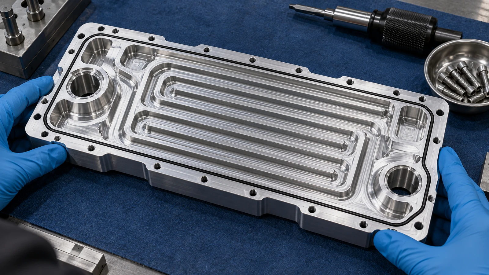
The coolant layout needs to be reviewed alongside the mounting pattern. Channels should not remove material required for a fastener, insert, or sealing land. Port locations should permit hose or fitting installation without interfering with adjacent enclosures, covers, or service tools. Cross-drilled access holes, if used, need a defined closure method and a plan for deburring and cleaning.
Seal geometry is a separate design input from channel geometry. Specify the gasket or O-ring type, groove dimensions, compression approach, and the surface condition required at the sealing land. Check the full bolt pattern for even clamping; an edge groove too close to a port or mounting hole can leave insufficient material or make compression uneven.
A one-piece plate can reduce joints but may require deeper machining or longer tools. A joined construction can make internal channels easier to form, yet introduces a bond, braze, weld, or gasketed interface that must be manufactured and verified. Select an architecture based on the coolant, operating environment, service approach, volume, and required proof. Do not compare only the number of parts.
Protect the mounting and contact datums
Mounting faces and thermal faces often interact. If the plate is clamped through several points, the installed shape can differ from the unrestrained shape. Define the datum scheme from the actual module interface and show where the part is supported during inspection. A flatness result measured on an arbitrary table may not predict contact after the plate is bolted to the tool frame.
Thin regions between channels, deep pockets, and asymmetric port bosses can release residual stress during material removal. A process review may adjust the roughing and finishing order, leave support stock until later operations, or inspect after the part has relaxed. These are design-specific decisions; no universal machining sequence guarantees a particular flatness result.
Specify which holes locate the part and which are clearance or service features. Tightening every hole position can add cost without improving the interface. Conversely, a poorly defined datum can make port alignment and thermal contact difficult to reproduce. The drawing should identify functional relationships rather than simply accumulate dimensions.
Choose a construction route for the design stage
CNC machining from plate or billet can be appropriate for a prototype or a design with accessible internal channels and critical faces. A cover plate or joined construction can support a different channel layout, but adds a joining and leak-verification step. Sheet metal fabrication may suit a broad enclosure or coolant guard around a cold plate, though it is not a direct substitute for a precision fluid-bearing thermal interface.
The site offers CNC machining capabilities for drawing-based parts and metal surface finishing services for defined post-processing needs. A prototype build can help confirm port access and assembly, but its material, joint method, and internal passage finish should represent the intended evidence. A fit prototype is not automatically a thermal or pressure-qualified production design.
When the final architecture is not fixed, compare routes against the evidence required: internal channel access, leak testing, contact-face finishing, cleaning, repair, and expected volume. A supplier DFM review is most useful when the thermal and coolant interfaces are included in the same model as adjacent components.
Match material and coolant interfaces
Aluminum can be selected for a combination of low mass, machinability, and thermal conduction. Copper may be considered when the design specifically needs its thermal properties and can accommodate its density, cost, and joining or finishing requirements. Stainless steel may be relevant for certain coolant or environment constraints, but its thermal behavior differs. Material selection should be based on system requirements, not a ranking that ignores geometry and fluid compatibility.
Coolant chemistry and sealing materials need review with the equipment designer. The fluid may interact with the base alloy, coating, joining material, gasket, or debris trapped in a channel. Specify the approved fluid and any corrosion, contamination, or cleaning restrictions. If a surface treatment is used, confirm that it does not compromise the contact face, seal, or coolant path.
Die aluminum machining page und copper machining page provide starting points for process discussion. Final grade, temper, surface condition, and compatibility should be established in the controlled drawing and approved material documentation.
Separate dimensional, leak, and thermal evidence
Dimensional inspection checks features such as mounting-hole position, contact-face geometry, groove dimensions, and port location. Leak verification addresses the fluid boundary under a defined test setup. Thermal verification evaluates the assembled plate with the relevant heat source, coolant, flow, sensors, and boundary conditions. Each test answers a different question and should have its own method and acceptance criteria.
For a leak test, state the test medium, pressure or vacuum condition, duration, instrumentation, and acceptance rule. If the plate contains plugs or joined covers, define whether the test occurs before or after those operations. A successful test only applies to the tested configuration; it does not prove that the contact face has the required thermal behavior.
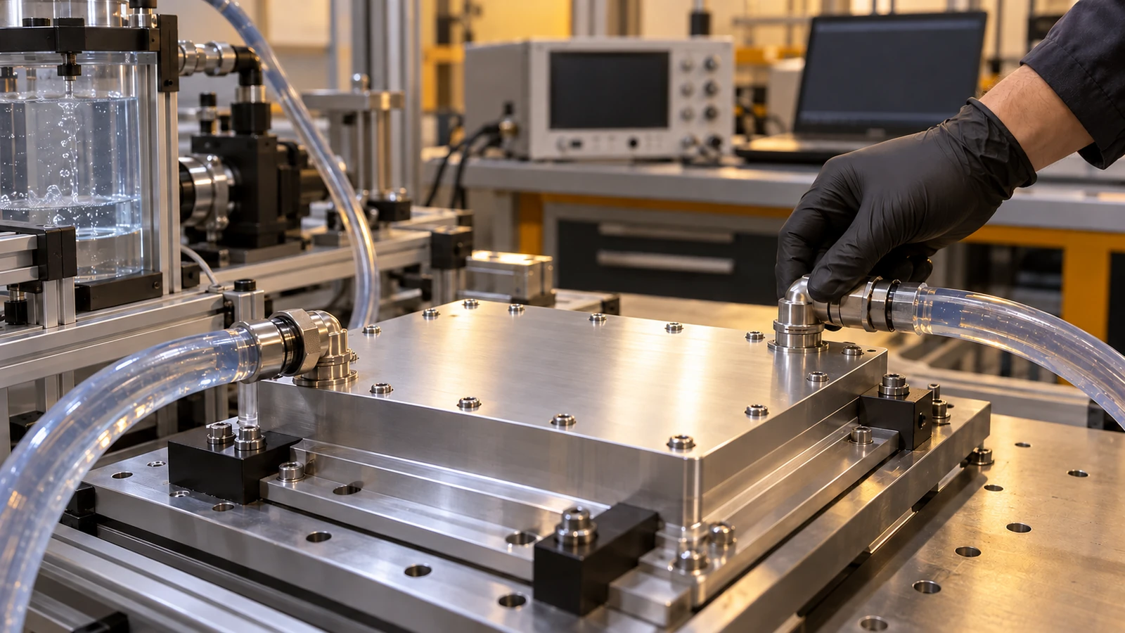
For a thermal test, capture assembly torque or clamping method, interface material, coolant conditions, heat load, sensor positions, and stabilization approach if the design authority requires them. Do not publish a performance number without its test context. If the project is still at prototype stage, report what the prototype was built to learn and keep the result distinct from production capability.
A practical cold-plate RFQ checklist
Provide the 3D model, controlled drawing, channel and port definition, coolant and seal requirements, contact-face datums, material grade, finish, quantity, revision, and inspection plan. Include adjacent module geometry and the assembly orientation. Mark any surfaces that require masking or special handling and identify whether the supplier is quoting an unjoined body, a completed plate, or an assembled fluid circuit.
Ask the supplier to review channel access, remaining wall sections, tool reach, deburring, plug installation, finishing sequence, flatness after material removal, and test access. If the flow or thermal model is not final, label the assumptions and identify which features may change. That lets the manufacturing plan support iteration without confusing a provisional configuration with an approved design.
A semiconductor equipment cold plate succeeds when fluid, thermal, and mechanical interfaces remain coordinated from model to inspection. Keep each requirement tied to a datum, process step, or test, and the part can be evaluated as a real equipment component rather than a generic machined plate.

