


A fuel rail can look like a straightforward bar with ports, yet its internal passages and sealing interfaces make the machining route consequential. A drilled gallery that intersects another bore leaves a burr risk at the junction. A mounting face that shifts during setup can change injector position. Chips or residue left behind may compromise a component that is expected to deliver fuel consistently. The challenge is not simply making holes; it is controlling the relationships between flow paths, interfaces, cleanliness, and evidence.
For an engineering team, automotive fuel rail machining should start with the drawing, material specification, fuel-system architecture, and cleanliness expectations. The manufacturing plan then turns those requirements into datum choices, operation order, deburring access, inspection points, and a route for protecting finished surfaces. This guide focuses on those decisions and on the information that helps a supplier quote and produce a rail without guessing at design intent.
Contents
- Define the rail’s functional interfaces
- Plan intersecting passages before cutting
- Choose a route that protects datum relationships
- Make deburring and cleanliness part of the process
- Inspect features against their function
- Prepare a useful manufacturing package
- Frequently asked questions
Define the rail’s functional interfaces
Begin by separating the rail into functional groups. The fuel gallery carries flow; injector ports locate and seal injectors; end connections interface with lines or fittings; mounting features hold the assembly relative to the engine; and sensor or regulator ports support system-specific hardware. Each group may have different tolerances and inspection needs. Treating every dimension as equally critical can add cost without improving performance, while failing to identify a critical sealing or positional relationship can create avoidable fit problems.
Build a feature map from the controlled drawing. Identify the primary mounting datum, the rail axis or gallery centerline, injector center positions, port orientations, sealing faces, and any end-to-end alignment requirement. Then note which dimensions are basic, which are toleranced, and which depend on a geometric tolerance frame. If a drawing calls out position relative to a datum reference frame, the inspection setup should reproduce that reference scheme rather than measure each hole from a convenient unrelated edge.
Material must also be tied to the approved specification. Aluminum, stainless steel, or another alloy can imply different cutting behavior, corrosion considerations, joining routes, and surface treatment constraints. Do not select a grade because it is commonly used elsewhere; confirm alloy, temper or condition, product form, and traceability requirements with the design authority. For an aluminum rail, the site’s CNC aluminum material information can help frame the discussion, but the released drawing remains controlling.
Plan intersecting passages before cutting
Cross-drilled passages create the central process-planning problem. A drill that breaks into a main gallery can leave a lip at the intersection, and the burr may be difficult to see from the entry face. The designer and manufacturer should identify every intersection, the likely burr direction, the tool approach, and the method for confirming that the edge is controlled. Depending on geometry, options can include a defined deburring operation, accessible edge breaks, specialized tools, process sequence changes, or design adjustments. The right choice depends on the passage geometry and the drawing, not on a generic promise that a part is burr-free.
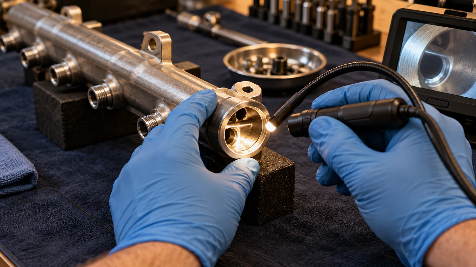
Before release, review whether the ports can be reached with standard tooling, whether deep-hole drilling produces adequate chip evacuation, and whether a later operation will intersect or distort a previously finished seat. If a passage is unusually long relative to its diameter, discuss drill wander and the inspection method. A flow path should be dimensioned and inspected in a way that makes its functional requirement measurable. If the design intent concerns connectivity or pressure loss, that requirement needs a defined test or acceptance method rather than an informal visual judgment.
In early development, a machined prototype can help evaluate access, assembly, and the sequence for cleaning intersecting passages before production tooling or a larger release quantity is committed. For a supplier with CNC turning and milling capabilities, a conversation about CNC machining operations should include the part’s passage map and datum scheme, not just the outside dimensions.
Choose a route that protects datum relationships
The operation sequence should reduce repeated setups and preserve the relationships that matter. A typical route may establish a stable reference face and axis, create the main body and gallery, machine intersecting ports, finish injector seats and mounting surfaces, deburr, clean, and inspect. This is an example for discussion, not a universal recipe: a rail made from bar, extrusion, forging, casting, or a joined assembly can require a different route. The starting form, stock allowance, production quantity, and geometry all affect the sensible sequence.
| Planning decision | Why it matters | What to clarify |
|---|---|---|
| Primary datum | Controls setup transfer and feature location | Which drawing datum represents assembly function? |
| Passage sequence | Affects burr direction, tool access, and chip removal | Where do bores intersect, and how will those edges be checked? |
| Seat finishing | Protects sealing and injector alignment | Which faces or seats require final sizing after roughing? |
| Cleaning stage | Reduces retained chips and process residue | What cleanliness evidence and packaging are required? |
Roughing and finishing should be considered separately when material removal or clamping can move the part. Leave appropriate stock on sensitive faces, release the part from the fixture when the route requires stress relief or stabilization, and finish critical features from a controlled reference. The exact approach depends on the material and geometry. If a component is cast or formed before machining, blank variation and allowance must be understood before selecting finishing operations. The project team can compare these considerations with the site’s die casting capabilities when the released design actually calls for a cast starting form.
Make deburring and cleanliness part of the process
Deburring is not a cosmetic step on a fluid-handling component. It has to address intersecting edges, port entrances, sealing faces, and any location where a loose fragment could remain. Specify acceptable edge conditions and protect critical seats from abrasive contact. A process plan should state when deburring occurs relative to final sizing and inspection, because a later tool can recreate a burr after an earlier cleanup.
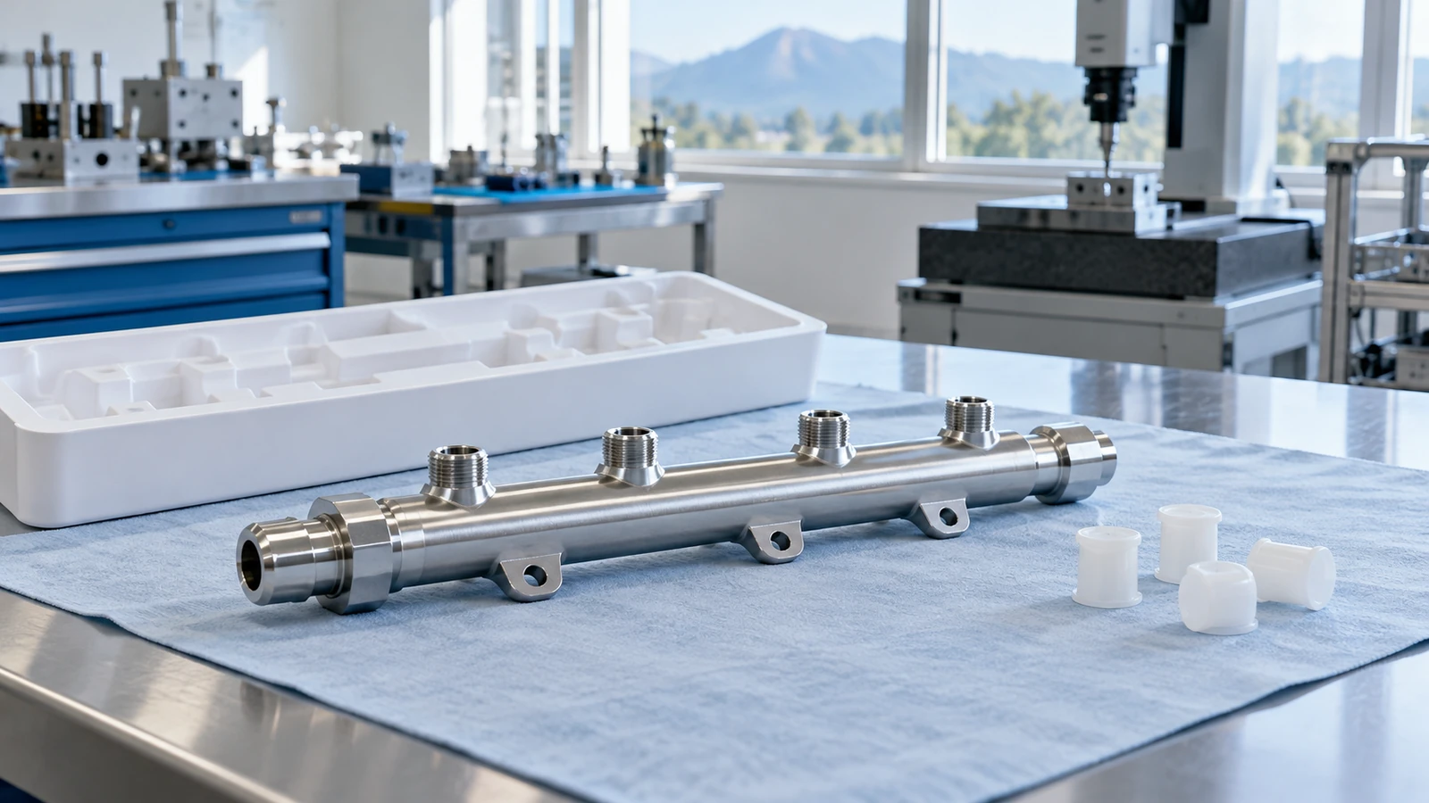
Cleaning also needs a defined endpoint. Consider the contamination sources in machining: chips, cutting fluid, abrasive media, lint, handling residue, and packaging. A useful requirement identifies the expected cleanliness level, the inspection or verification method, and how the rail is protected afterward. Avoid vague wording such as “clean to standard” unless the standard and acceptance method are named. If the application requires a validated cleanliness protocol, that protocol must come from the customer or governing design documentation; it should not be invented by the supplier.
Surface treatment or coating may affect dimensions, corrosion behavior, sealing, and cleanliness. If specified, define which areas are treated, which must be masked, and how post-treatment dimensions are verified. The site’s surface finishing service overview can support an early process conversation, but compatibility and acceptance criteria should be confirmed for the actual fuel, environment, and assembly.
Inspect features against their function
Inspection should combine dimensional checks with any required functional tests. Depending on the drawing, this can include the location and size of injector bores, thread or fitting gauges, sealing-face finish, port position, gallery geometry, overall straightness, and the relationship between mounting datums and functional features. A coordinate measuring machine may suit accessible external geometry; specialized gauges or fixtures may be needed for production checks. Deep internal passages can require a method agreed in advance, because a standard probe may not reach or characterize the feature.
Leak, flow, or pressure testing is not automatically implied by the part name. If such a test is required, specify the medium, pressure, duration, temperature where relevant, fixture interfaces, acceptance threshold, and record format. A process capability claim also needs a defined population and measurement method. For a one-off prototype, the evidence package may emphasize first-article dimensions and design review; for repeat production, the buyer may need a control plan, sampling approach, lot traceability, and documented nonconformance handling.
Inspection records are most useful when they map back to drawing characteristics and revision. Agree which features receive a report, how serial or lot identity is recorded, and whether material certificates or treatment records are part of the delivery package. This makes incoming review faster and avoids disputes about what was actually verified.
Prepare a useful manufacturing package
A quote request should include the released drawing or model, revision, quantity range, material and condition, finish requirements, critical-to-function characteristics, cleanliness instructions, test requirements, and packaging expectations. Identify which dimensions are reference only and which require recorded inspection. If the geometry contains internal passages, provide section views or a passage map so the supplier can identify tool access and deburring risks.
For a design that is not fully released, label the model as preliminary and list the open decisions. A supplier can help assess manufacturability, but should not silently resolve contradictory drawing notes or guess a pressure-test requirement. A structured design-for-manufacturing review is particularly useful before the injector locations, end fittings, or mounting datums are frozen.
When reviewing a quotation, compare more than unit price. Check assumptions about starting stock, setup count, inspection scope, deburring, cleaning, outside processing, lead-time basis, and change control. A low price that omits passage verification or packaging may not be comparable to a quote that includes them. Clarify whether material substitution is prohibited and who approves deviations.
Frequently asked questions
What makes a fuel rail difficult to machine?
The combination of intersecting internal passages, injector and fitting interfaces, datum relationships, burr access, and cleanliness requirements creates the main planning challenge. The geometry and approved material determine which issue dominates.
Does every fuel rail require a leak or flow test?
No universal test requirement follows from the component name. The drawing, customer specification, and intended validation plan should define whether a leak, pressure, or flow test is required and how results are recorded.
Can a machined prototype validate production performance?
A prototype can answer specific questions about geometry, assembly, access, or a defined test. It does not automatically establish production capability or validate requirements that were not included in the prototype’s test plan.

