


An outdoor EV charger enclosure is not simply a metal box with a weather rating. It carries power electronics, communication hardware, cooling components, user interfaces, cables, and service access into a public environment where rain, sun, dust, impact, vandalism, installation errors, and repeated handling occur together.
Reliable EV charger enclosure design therefore begins with the charger’s working life. The housing must protect people and electronics during transport, installation, charging, cleaning, and repair while preserving heat flow, cable geometry, structural support, electromagnetic control, and repeatable manufacturing.
Follow the Charger Through Its Working Life
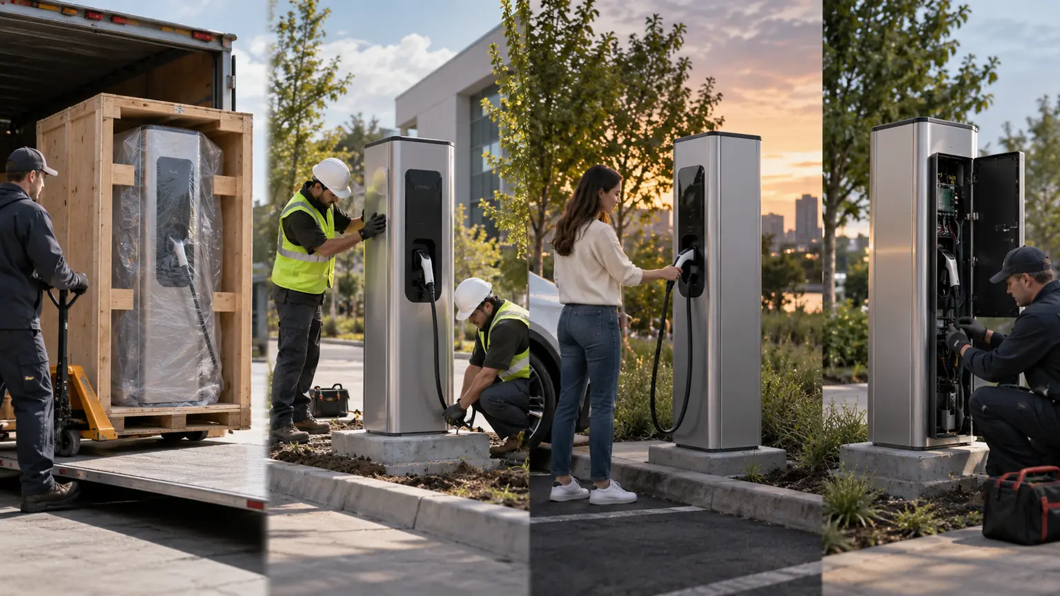
A design review should follow the unit before it is powered. Shipping loads reach the cabinet through its base, lifting points, pallet, internal modules, and protective packaging. A tall charger that looks stable in CAD may twist when lifted or lean when moved across an uneven installation site.
Installation introduces a different set of forces. Anchor bolts need tool access, base plates must tolerate site variation, cable conduits require realistic bend radius, and sealing details must remain intact after electricians pull cables through them. If the mounting plane is not flat, the enclosure should not depend on uncontrolled site torque to pull it into shape.
Daily use loads the cable holster, connector support, screen bezel, door seams, payment-module area, and any surface users push or lean against. Service work then asks the enclosure to hold open safely, retain loose hardware, expose replaceable modules, and protect live or sensitive zones from accidental contact.
This lifecycle view creates a useful requirement list: shipping orientation, lifting method, anchor loads, public contact zones, cable forces, cleaning practice, access frequency, module replacement route, and expected environmental exposure.
Divide the Enclosure by Function and Risk
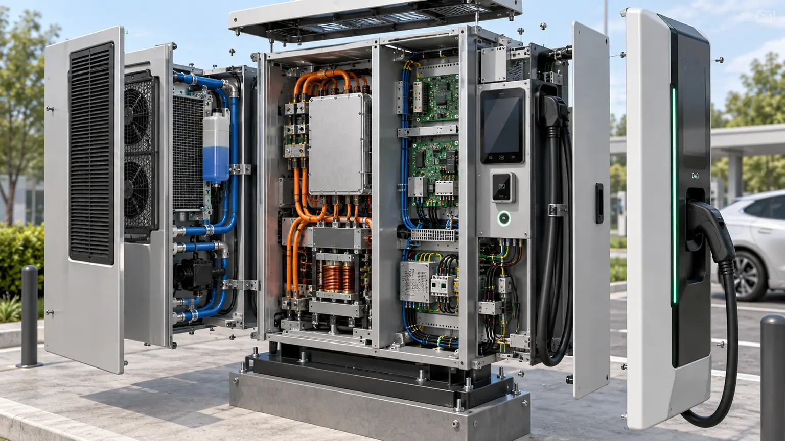
Internal zoning prevents one subsystem from creating problems for another. The enclosure should separate high-voltage power, low-voltage controls, communications, airflow, cable termination, and technician access according to the charger’s architecture.
| Zone | What it needs from the enclosure | Common conflict |
|---|---|---|
| Power conversion | Rigid mounting, heat path, electrical clearance | Cooling hardware blocks service access |
| Control and communications | Shielding continuity, low heat, cable separation | Noise from power cables and apertures |
| User interface | Visibility, impact support, weather protection | Large openings weaken the front panel |
| Cable termination | Bend radius, strain relief, tool clearance | Field routing loads glands and seals |
| Service bay | Safe reach, removable modules, retained fasteners | Technician must disturb unrelated parts |
Partitions can support more than safety. They can guide air, stiffen broad panels, carry wiring clips, shield communication boards, and establish repeatable assembly datums. Their position should be coordinated with the actual sequence used to install busbars, cables, fans, filters, and electronic modules.
Grounding and electromagnetic compatibility also belong in the mechanical layout. Painted seams, insulating gaskets, detachable panels, vents, and display openings can interrupt conductive paths. Define bonding points, masking, washers, fasteners, and verification instead of assuming that all metal parts are automatically connected.
Outdoor Survival Is Decided at Seams and Openings
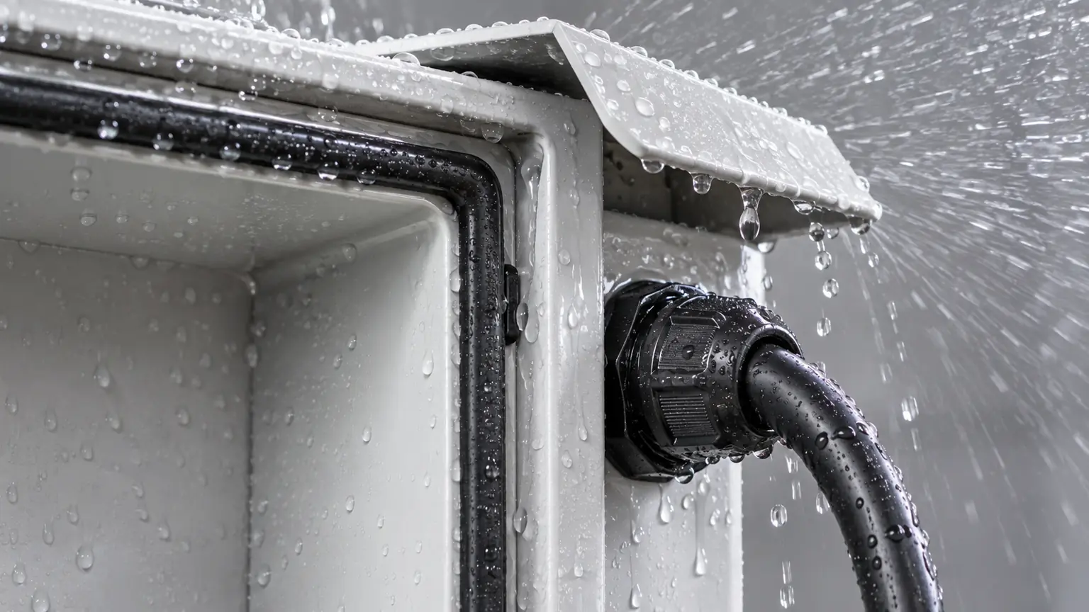
Rain rarely passes through an undamaged flat wall. It reaches the electronics through door corners, cable glands, display windows, vents, emergency controls, handles, roof joints, fastener penetrations, and surfaces that collect water. Review each opening in its installed orientation and under wind-driven exposure.
Use geometry as the first defense. Sloped tops, drip edges, recessed doors, overlapping seams, labyrinth paths, sheltered vents, and drainage reduce the amount of water presented to a seal. A gasket should provide the final controlled barrier rather than compensate for a flat surface that funnels water toward the joint.
Door compression must remain stable
Specify gasket compression range, flange width, surface condition, latch spacing, hinge support, fastener torque, compression stops, and the accumulated tolerances around the perimeter. Welding and coating can move the sealing plane after the CAD design is complete.
Corrosion protection must include cut edges, welds, fastener pockets, drains, grounding masks, and dissimilar-metal interfaces. A qualified surface finishing process should be tested on representative enclosure geometry rather than only on a flat coupon.
Heat Must Reach the Outside Without Bringing Weather In
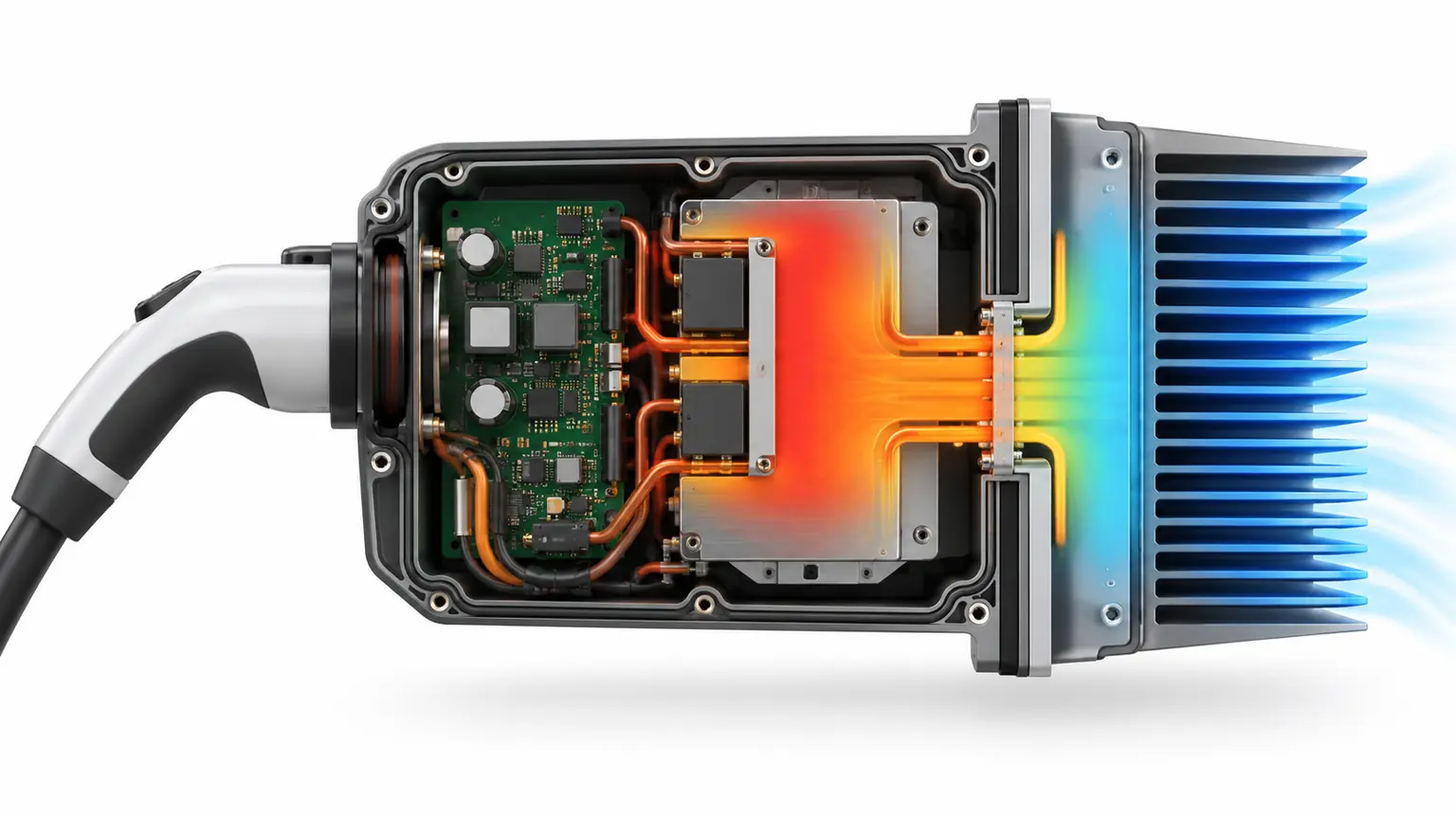
Power modules, contactors, busbars, filters, control boards, and charging cables create different heat loads. Map continuous loss, peak operation, solar gain, adjacent-unit effects, and the hottest permitted site condition. Then trace each thermal path from the component to air, liquid, a heat sink, or the enclosure wall.
Open ventilation is simple but brings dust, moisture, insects, and filter maintenance. Closed-loop air conditioning supports a sealed internal volume but adds condensate and service requirements. Conductive cooling through an external heat sink can protect the internal air path, yet the thermal interface and weather seal may compete for the same surface.
Where a power module mounts to a heat spreader or cold plate, flatness, contact area, surface finish, interface material, fastener pattern, and torque all influence performance. CNC-Bearbeitung is useful for prototype thermal plates and precise mounting interfaces because geometry can change without dedicated tooling.
Condensation deserves a separate review. Night cooling, morning sun, power cycling, air exchange, and service-door opening can move internal surfaces below dew point. Venting, heaters, insulation, drains, coatings, sensor placement, and control logic should be considered as one moisture strategy.
Choose Processes by Part Function
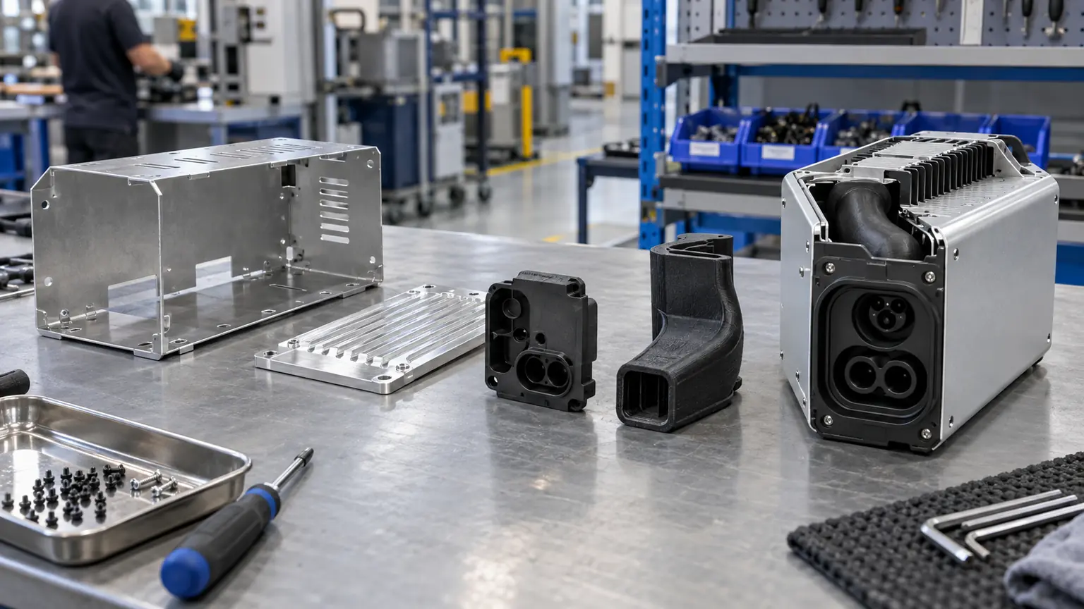
The main frame and doors often favor Blechbearbeitung because bends, returns, beads, welds, and inserted hardware create large stiff structures economically. Broad flat panels should be reviewed for oil canning, vibration, cosmetic reflection, and distortion around welds or cutouts.
Machined parts are appropriate where the enclosure needs accurate sealing lands, thermal contacts, bearing surfaces, connector bores, hinge blocks, or anchor interfaces. Molded plastics can integrate bezels, cable guides, insulating barriers, holsters, and user-facing shapes. Die-cast components can combine ribs, bosses, heat-spreading features, and repeatable medium-to-high-volume geometry.
The production route changes the design rules. Sheet metal needs feasible bends and weld access. Molding needs draft, stable wall transitions, gates, ejector strategy, and insert control. Die casting needs draft, overflow and vent planning, porosity control, and secondary-machining allowance. A prototype should answer the risks of the intended route rather than merely imitate the final appearance.
Jucheng Precision’s prototyping service can combine fabricated metalwork, machined thermal parts, printed ducts or bezels, finishes, and assembly checks in a single functional charger build.
Prototype Test Matrix Before Tooling
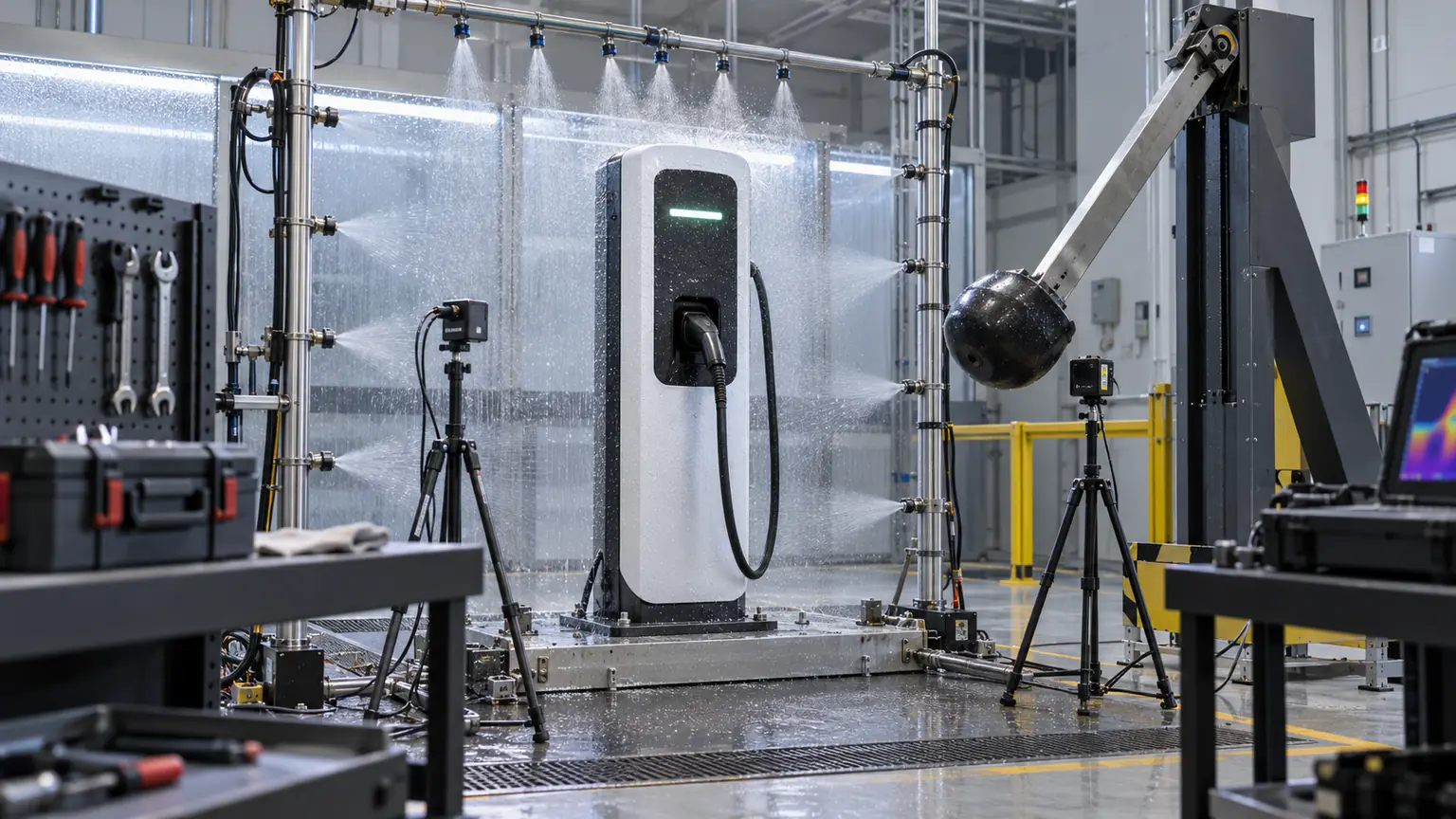
Do not ask one polished prototype to answer every question. Build a small test matrix in which each specimen has a defined purpose and acceptance rule.
| Prototyp | Primary question | Evidence to collect |
|---|---|---|
| Shipping frame | Do lifting and transport loads preserve alignment? | Datum shift, door fit, fastener condition |
| Weather corner | Where can water cross or collect? | Entry path, gasket contact, drainage |
| Thermal spine | Does heat reach the rejection surface? | Interface temperature, flatness, torque |
| Service bay | Can modules be replaced safely? | Tool access, cable strain, task sequence |
| Pilot enclosure | Can the process repeat critical geometry? | Sealing-plane data, finish, dimensional capability |
Inspect before and after environmental or mechanical testing. Record sealing-plane flatness, latch and hinge alignment, anchor geometry, cable-entry position, thermal-contact surfaces, coating condition, and the dimensions that locate internal modules. A pass/fail result without teardown evidence may hide the mechanism that will reappear in production.
System-level electrical safety, ingress, thermal, impact, and compliance testing depends on the completed charger, installation conditions, and approved standards. The enclosure supplier can manufacture representative specimens and verify agreed dimensions or process controls, while the product owner defines and approves the final qualification plan.
EV Charger Enclosure FAQ
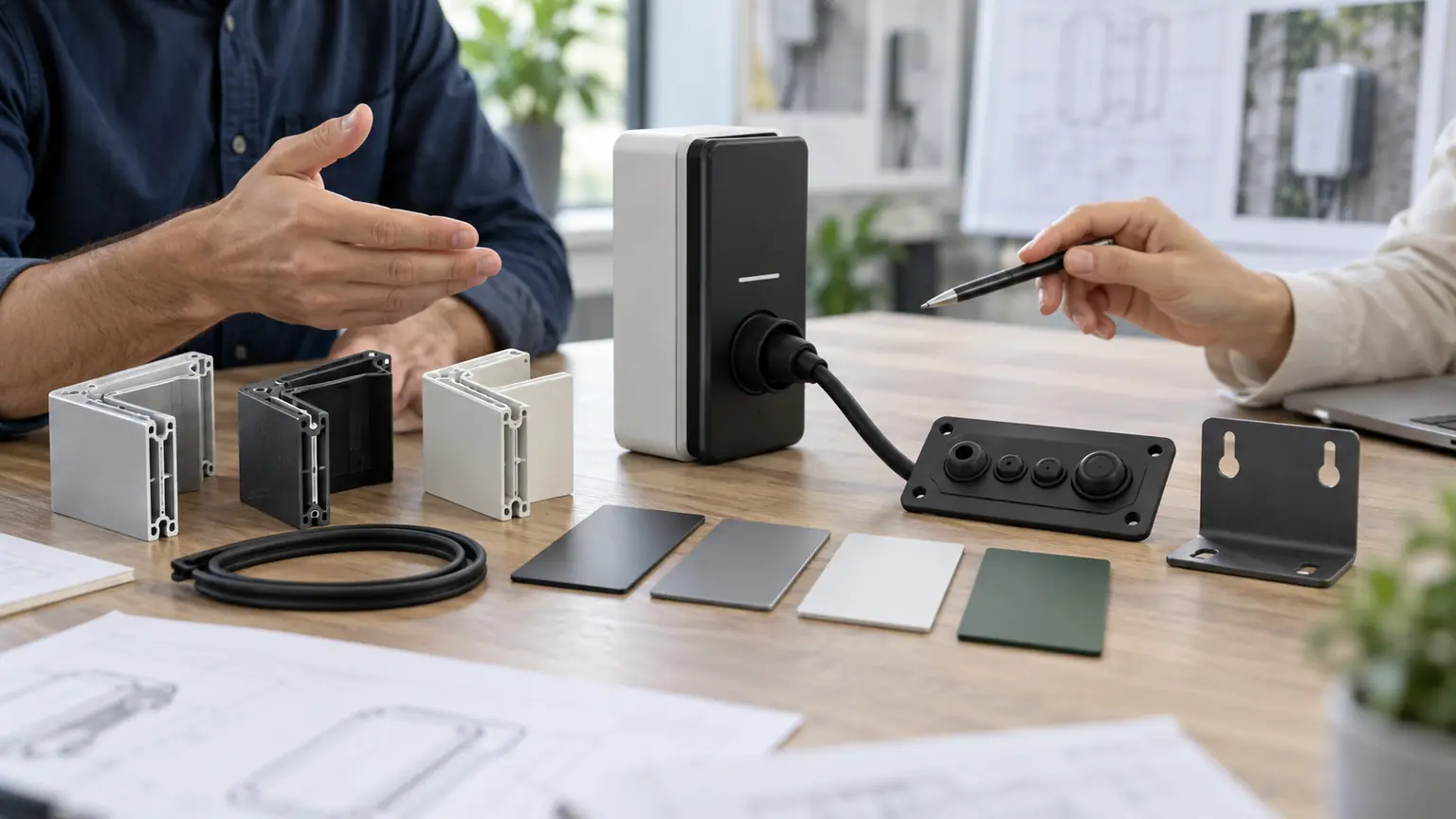
Which material is best for an outdoor EV charger?
There is no universal choice. Coated steel offers economical stiffness, aluminum reduces weight and spreads heat, stainless steel supports aggressive environments, and plastics serve windows, bezels, insulation, and shaped user interfaces. Select the complete material and finish system against the site and manufacturing route.
Does a high ingress rating solve every moisture problem?
No. The rating applies to a defined test condition. Condensation, pooled water, damaged seals, cable installation, pressure cycling, maintenance, and long-term coating degradation require additional design and validation.
Should the enclosure be designed before the electronics layout?
No. Power-module position, cable routing, cooling, communications, service access, shielding, and safety zones all change the metalwork. Mechanical and electrical architecture should develop together.
What should suppliers receive with an RFQ?
Provide the operating environment, annual quantity, CAD and drawings, functional datums, critical tolerances, materials, finish, sealing surfaces, hardware, cosmetic zones, inspection method, test responsibility, and expected prototype purpose.
The Enclosure Connects Every Subsystem
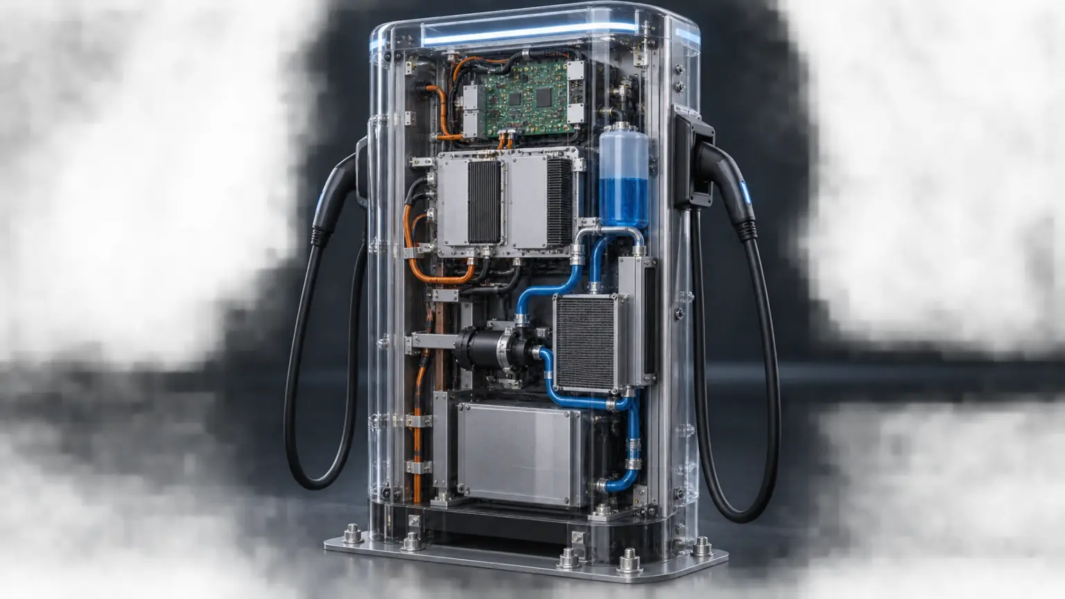
A durable EV charger enclosure succeeds because structure, weather protection, thermal management, electrical separation, cable handling, service access, and manufacturing reinforce one another. Following the charger through its real working life exposes those connections early—when geometry and process choices are still inexpensive to change.

