


The implant connection is the detail that sets the machining priorities for a dental abutment. The visible contour matters, but the internal connection, seating face, screw channel, axis, and emergence profile have to be defined in relation to one another. A part can look polished and still be unusable if the connection geometry or angular orientation does not match the controlled interface. This guide focuses on manufacturing definition and inspection; it does not give clinical or restorative advice. For development work, the site’s medical-device prototyping page provides the industry context. The design owner must supply the approved connection specification, material, revision, and acceptance criteria.
Contents
- Treat the implant interface as controlled geometry
- Sequence the connection and outer profile deliberately
- Specify the material and blank condition explicitly
- Separate connection finish from visible finish
- Verify the relationship, not just isolated sizes
- Keep the screw and mating stack within scope
- Prepare an abutment RFQ that can be quoted accurately
- Frequently asked questions
Treat the implant interface as controlled geometry
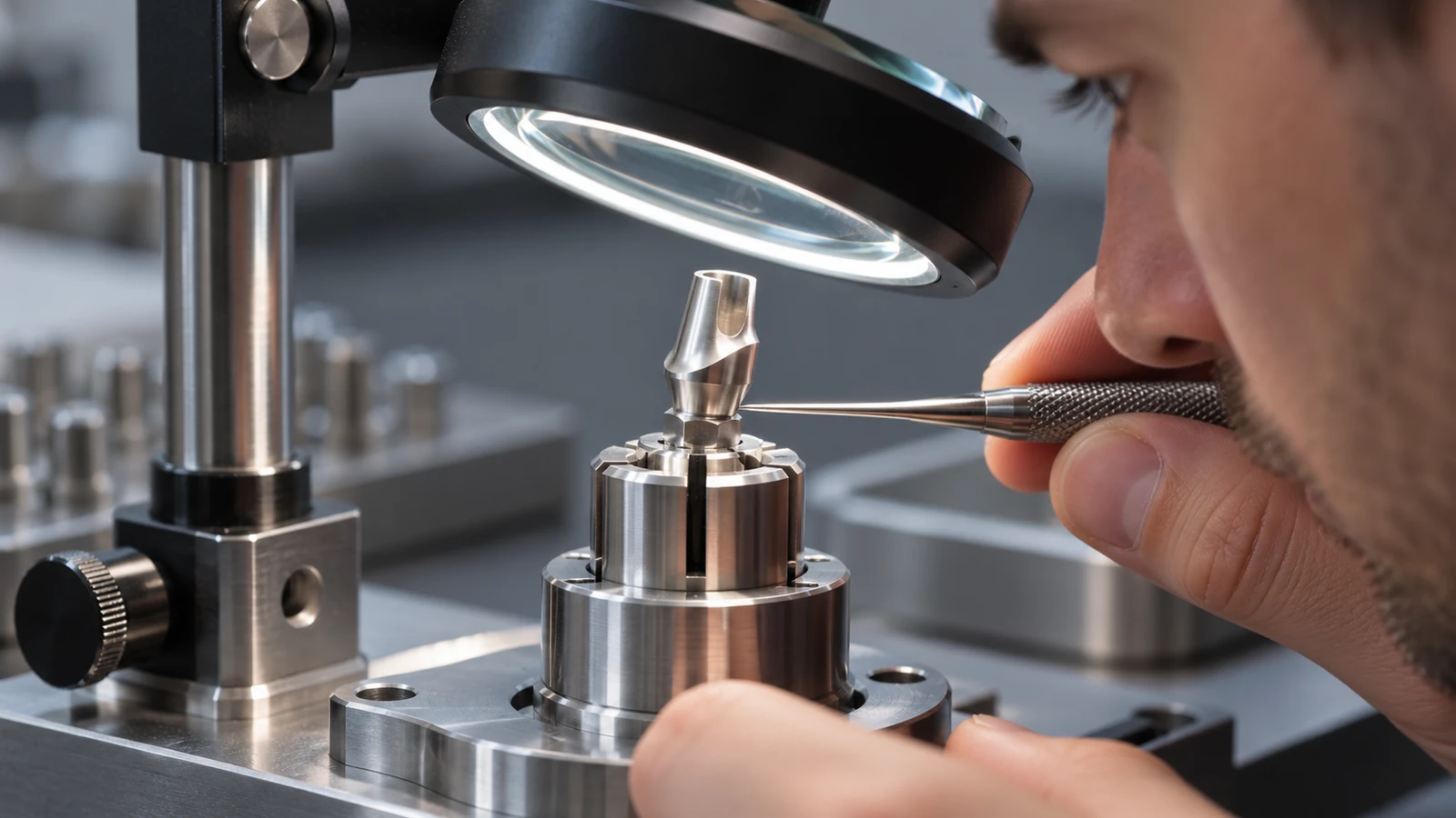
First establish which connection family and dimensions are specified by the customer. Do not infer compatibility from a photograph, brand name, or a nominal thread callout. The mating interface may include a tapered or indexed seat, anti-rotation geometry, a screw channel, and a defined seating face. Each feature needs the appropriate dimensions or controlled model definition, with revision and source clearly identified. Clarify whether the abutment is straight or angled and how angular orientation is referenced. A rotation error may not be obvious from a simple diameter check. The drawing should state the datum axis, indexing feature, and relationship between the connection and the external contour. This gives machining and inspection teams a common basis for setup and reporting.
Sequence the connection and outer profile deliberately
Small turned or milled features may require multiple orientations. If the connection is produced before the outer geometry, later clamping must not damage or distort the interface. If it is finished last, the setup needs to reference the established external features without losing the intended axis. The correct sequence depends on stock, machine access, material, and the design’s tolerance scheme. Review tool access to narrow internal seats and screw channels. Small cutters and long tools may limit reach or stiffness. Plan chip removal and deburring so no unwanted edge remains in the connection while intentionally specified corners or transitions are preserved. A process review should also confirm how the part is held for secondary finishing and which surfaces are protected.
Specify the material and blank condition explicitly
Dental abutments may be designed for specified titanium alloys or other material systems, including zirconia-based components in some product families. The exact grade, product form, condition, and approved processing route must come from the controlled design documents. This article does not assert that one material is clinically suitable or compatible with every implant system. Material affects machining behavior, surface treatment, and documentation requirements. Keep identity linked to part and lot records in line with the project’s quality plan. Do not substitute a material or infer a grade from color or appearance. Jucheng’s titanium machining page can support a manufacturing discussion when the specified material is titanium; the approved drawing and material specification remain authoritative.
Separate connection finish from visible finish
The implant connection and external contour may have different surface requirements. State the relevant surface parameters, where they apply, and how they are measured. A polished outer surface does not prove the interface seating face meets its requirement. Conversely, a functional connection may need a specific machined condition even if the visible contour receives further finishing. Clarify whether dimensions apply before or after surface treatment and identify areas that must be masked or protected. Finishing can affect edge definition and measurement. Specify the process only when it is part of the approved design route; do not add generic polishing or coating steps that could alter a critical interface.
Verify the relationship, not just isolated sizes
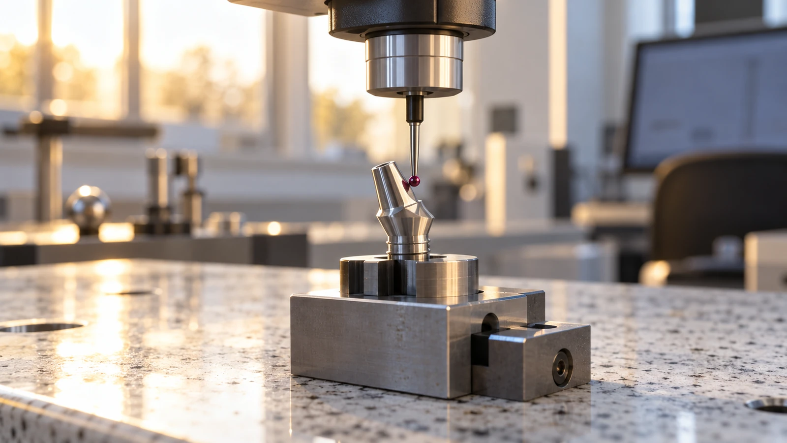
Inspection should check the connection geometry, seating face, screw channel, external profile, and indexing relationship in the datum frame defined by the drawing. A pin gauge or thread gauge may answer one question, but it cannot by itself verify position, taper, orientation, or profile. Choose measurement methods for the specified characteristics and document the setup used. For a prototype, agree on the critical features and report content before machining. If inspection equipment uses a representative mating gauge or reference component, identify its status and the characteristic it verifies. Preserve part identification, drawing revision, material record, and inspection results under the project’s documentation rules. Dimensional inspection does not establish clinical outcome or regulatory approval.
Keep the screw and mating stack within scope
The screw channel and seating geometry work with other components. If the customer expects an assembly check, supply the controlled mating parts or their interface specifications and define the fit evaluation. Do not assume a screw that enters a channel proves that the connection is correct; thread engagement, seating, orientation, and interface contact may be separate requirements. Distinguish a component check from a full restorative or clinical assessment. A manufacturing supplier can report dimensions and agreed assembly observations, but clinical appropriateness is outside the scope of a machining report. This boundary keeps the acceptance criteria measurable and prevents marketing language from overstating what a prototype demonstrates.
Prepare an abutment RFQ that can be quoted accurately
Include the controlled drawing and model, connection specification and revision, material and condition, quantity, finishing instructions, inspection requirements, and any approved mating reference needed for verification. State whether the build is for fit study, design development, or another defined stage. Mark angular orientation, seating surfaces, critical axes, and areas where handling marks are not acceptable. Ask the supplier to identify any missing connection dimensions, inaccessible measurement points, or unclear post-processing requirements before production. The medical-device tolerance guide can help structure a broader discussion about tolerance allocation, but project acceptance remains governed by the controlled drawing and design authority.
Frequently asked questions
Can an abutment be made from a generic implant-interface model?
No. Use the controlled interface definition and its revision. Visual similarity does not establish compatibility.
Does a thread gauge confirm the full connection?
No. It may verify a thread characteristic, but the seating surface, axis, indexing geometry, and other defined features need their own checks.
Can machining inspection establish clinical suitability?
No. It documents manufacturing characteristics. Clinical and regulatory decisions require separate processes under the responsible design authority.