


A trial component may resemble an implant and carry the same size label, yet still fail to support a useful design review if its interfaces, geometry, or identification are inconsistent across the family. In development programs, teams may compare several sizes or configurations before a released implant design is fixed. The manufacturing task is to keep the trial pieces traceable to the intended revision and to make their geometry and acceptance scope clear.
This guide discusses orthopedic trial implant machining from a custom-component perspective. “Trial” can mean different things across device programs, so the intended use and regulatory status must be defined by the device manufacturer. The article focuses on geometry, family management, materials, machining, and inspection handoff; it does not give patient-specific or clinical selection advice.
Contents
- Define what “trial” means in the program
- Control the size family as a configuration system
- Protect interfaces shared with instruments and fixtures
- Specify material and surface intent without assumptions
- Keep machining and identification linked to revision
- Build a report that makes comparison possible
- Frequently asked questions
Define what “trial” means in the program
Before quoting, state whether the item is a nonfunctional form model, an engineering prototype, a dimensional comparison part, a test article, a reusable instrument component, or a regulated device element. The name “trial implant” is not enough to establish material, cleanliness, surface, traceability, or validation requirements. Those can vary substantially by intended use and program stage.
Write down the question the part is meant to answer. Is the team comparing external envelopes? Checking an interface to an instrument? Evaluating a size family’s increments? Reviewing assembly access? Each objective drives different characteristics and records. A model intended for visual comparison may not need the same material or finish as a component used in a controlled functional evaluation. The device owner must determine what is acceptable.
Clarifying this scope also keeps manufacturing claims bounded. A machined part can be checked against a drawing and report. That does not by itself demonstrate clinical performance, biocompatibility, sterilization compatibility, or compliance. Separate those evidence needs and assign an owner for each stage.
Control the size family as a configuration system
Many trial components are supplied as families: several sizes, offsets, angles, or interface variants. A spreadsheet of labels is not a sufficient configuration definition. Each part needs a unique part number or variant identifier, drawing revision, and a clear list of changed characteristics. The size designation should correspond to controlled geometry, not merely to a marking added at the end.
Review the family for shared and variable features. Which mating interface remains common? Which dimension changes by size? Are offsets or angles stepped? Are there left/right or system-specific variations? A family matrix can map each identifier to its drawing, model, material, and inspection scope. This is especially helpful when a prototype order contains multiple sizes that look similar but require distinct setups or reports.
Plan marking so it remains readable without intruding on functional surfaces or creating a contamination, finish, or stress concern. If laser marking, engraving, or another identification method is requested, define the content, location, legibility, and whether marking occurs before or after finishing. Do not use a mark as the only revision control; the manufacturing traveler and inspection report should also identify the variant.
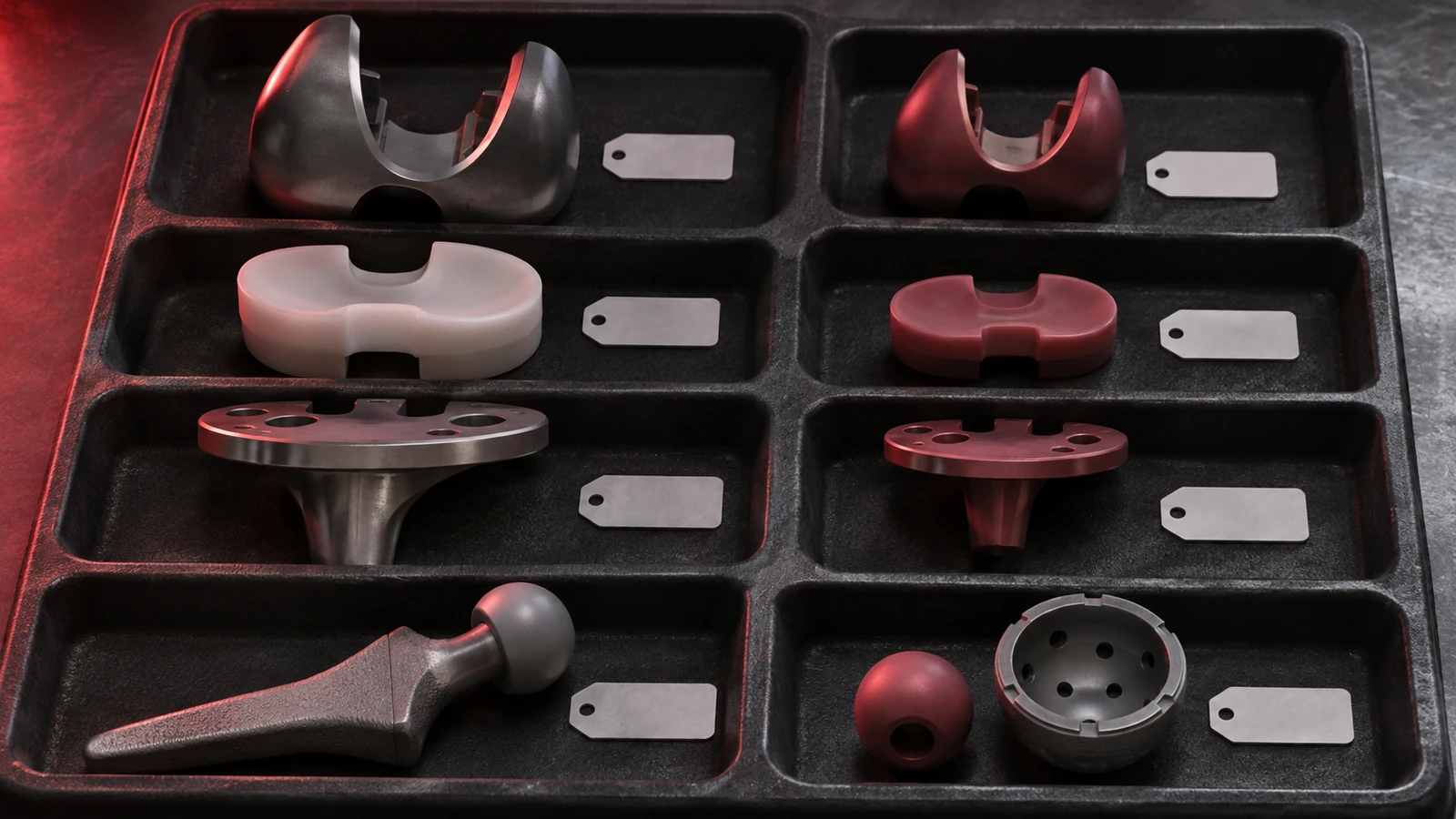
When geometry changes during development, issue a controlled revision and identify superseded parts. If a comparison set intentionally mixes revisions, list that explicitly and segregate the items. Otherwise a team may compare a new geometry with a prior variant while believing the labels are identical.
Protect interfaces shared with instruments and fixtures
Trial components may connect to handles, adapters, impactors, gauges, or test fixtures, depending on the system. Define the interface surfaces and their datums: engagement geometry, seating face, alignment axis, retention feature, and any clearance needed for assembly. The specific features are design-dependent; suppliers should not infer a universal orthopedic interface standard from a component description.
Where multiple sizes share one interface, confirm that the interface is truly common across all variants. A small change to a taper, slot, thread, or seating face can alter assembly even if the external envelope changes only slightly. If a mating instrument is customer-supplied, include its controlled revision or a representative interface drawing. If a gauge is used, specify what it simulates and whether it is the acceptance authority.
Relationship control matters more than a list of local sizes. A part can have an acceptable bore or engagement feature but be mislocated relative to the surface that seats against the fixture. Use the drawing’s datum reference frame to connect those features. The responsible design authority sets allowable variation and approves any proposed change.
Specify material and surface intent without assumptions
Material should follow the trial component’s defined role and intended evaluation. Some development items may use a material selected for geometry or handling review; other components may require a more representative material, finish, or processing route. Those decisions are program-specific. Do not substitute a generic “medical grade” statement for a precise grade, product form, condition, and required documentation.
Surface zones should also be described by purpose. A mating interface, visible contour, marking area, and nonfunctional relief may have different requirements. If polishing, passivation, coating, or other finishing is in scope, state what surfaces are included and whether dimensions apply before or after the operation. For a family, keep finish requirements consistent or mark the approved exceptions clearly.
Die medical device materials overview can help frame selection questions, while the exact grade and acceptance conditions must come from the device specification. If titanium machining is part of the approved drawing, Jucheng’s Ti-6Al-4V CNC machining page offers a material-process reference; it is not a substitute for device-level approval or material traceability.
Keep machining and identification linked to revision
A machined prototype can be useful when the family includes defined interfaces, bores, tapers, flats, or contoured surfaces that need to be compared. Process planning should distinguish common geometry from size-specific features. Shared datums or fixtures may improve consistency across a family, while different sizes may require unique workholding or tool access. The supplier should quote against the exact model and revision for each variant.
Roughing and finishing choices depend on geometry and stock. Deep pockets, thin walls, or asymmetrical material removal may affect stability. A staged sequence can leave allowance for final interface features after the part is supported by stable datums. This is a planning principle rather than a promised process recipe; actual setups depend on the supplied design, material, and machine access.
Prevent variant mixing through the complete route. Keep raw stock identification, traveler, operation sequence, inspection record, and final marking connected to the part number. When several pieces are machined together, separate them in a way that preserves identification after cutting. If post-processing is performed by another supplier, pass the revision and variant mapping with the parts and verify it on return.
For a development order, medical precision component manufacturing is a relevant starting point for discussing custom part scope. Confirm the exact operations, material sourcing, inspection, and documentation in the project quotation.
Build a report that makes comparison possible
For a size family, inspection should make differences and commonalities visible. A report can identify the part number, revision, nominal size or variant, material condition, measured characteristics, method, and inspection stage. The design owner decides which characteristics are critical. A report that lists many unrelated dimensions may still fail to compare the dimensions that distinguish one variant from another.
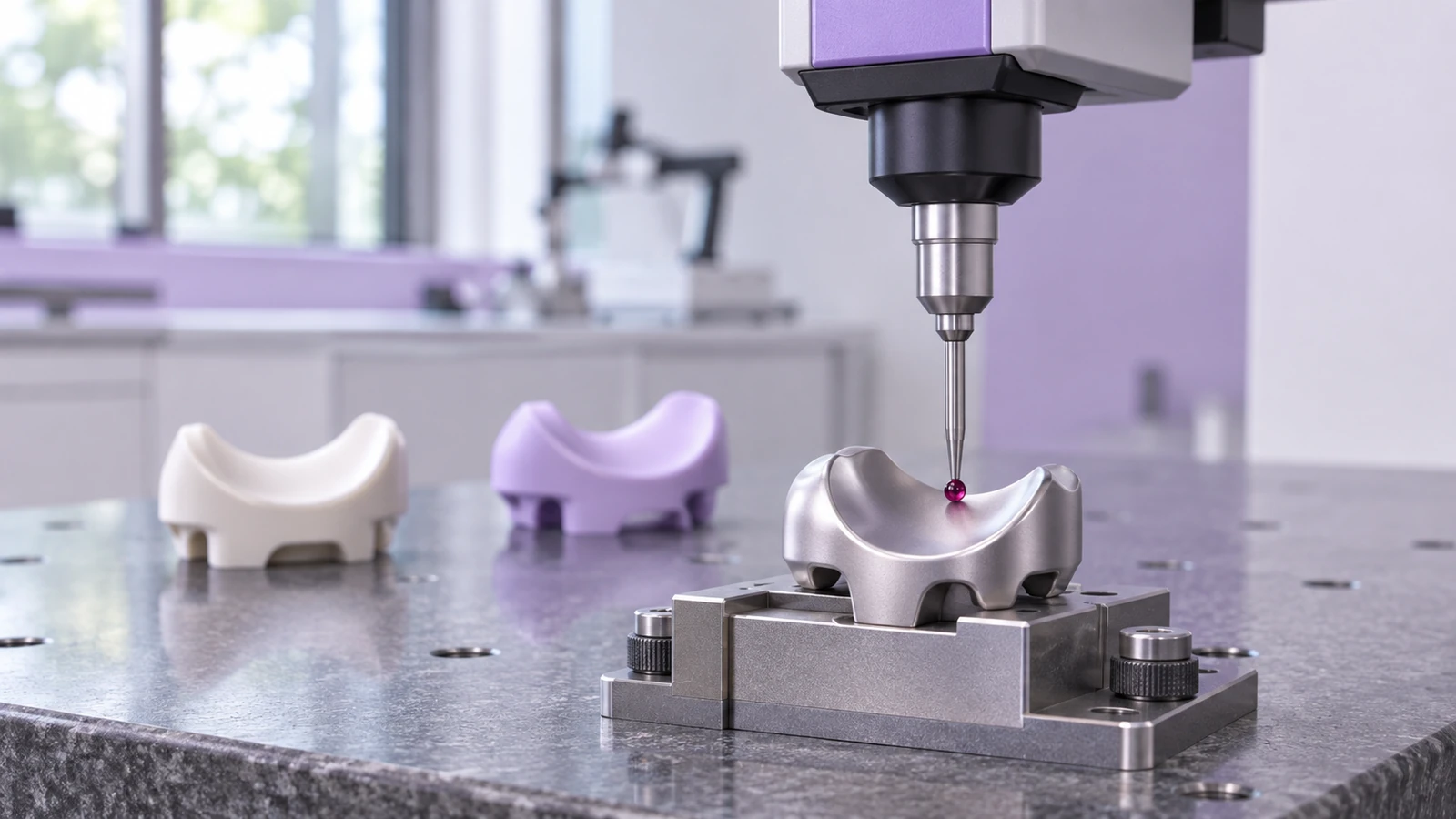
Consider a family comparison matrix with one column per variant and rows for the shared interface, variable geometry, and selected acceptance characteristics. It can reveal a swapped label, an unexpected offset, or a revision mismatch. The matrix is a traceability aid, not a tolerance specification; acceptance limits should remain on the controlled drawing or approved inspection plan.
Measurement conditions should be stated where they affect results. Does the component rest free-state? Is it held in a fixture? Is a mating insert installed? Are surfaces measured before or after finishing? For flexible geometry, the report may need to identify support and probe strategy. When a functional gauge is used, record gauge identity and calibration status as required by the program.
Frequently asked questions
Are trial implants the same as production implants?
Not necessarily. The term can describe different development or device-system components. The program owner must define intended use, material, processing, controls, and whether the item represents a production design.
How should multiple trial sizes be ordered?
Provide a controlled variant list with unique identifiers, drawing revisions, quantities, material, finish, and inspection scope for each size. Avoid relying on labels alone when geometry differs.
Does a dimensional report prove a trial component is clinically suitable?
No. It documents specified measurements under stated conditions. Device validation and clinical or regulatory decisions require separate evidence owned by the responsible manufacturer.
Trial-part programs become easier to manage when every size is tied to a controlled revision, every interface is defined from a datum, and every report supports a specific comparison. That discipline helps engineering teams learn from prototypes without confusing manufacturing evidence with broader device validation.

