


The housing has to serve more than the thermostat
A thermostat housing appears simple until its interfaces are considered together. It must locate the thermostat or cartridge, connect coolant ports, attach to an engine or hose, and seal against the mating face. Some designs are cast metal bodies with machined faces and bores; others use molded polymers or mixed assemblies. The right route depends on the drawing, operating environment, production quantity, and validation goal—not merely on the part name.
For an automotive thermostat housing manufacturing project, define the thermostat seat, port geometry, flange, fasteners, and sealing features before choosing casting, CNC machining, or molding. A useful article or supplier review should explain what each process can and cannot establish. Machining a prototype can confirm fit and port relationships, while a casting or molded sample may be required to evaluate wall structure, joining features, or production behavior.
Read the drawing as an interface map
Start by marking which features contact the thermostat, engine, hose, gasket, sensor, or cover. The primary locating face and the thermostat seat may need a controlled relationship; port centerlines may need to align with attached plumbing; the bolt pattern may define installation. These relationships should be tied to drawing datums. If the drawing only lists isolated dimensions, ask which interfaces control the assembly before planning the process.
Look for details that affect the production route: wall thickness, draft, ribs, bosses, undercuts, internal passages, and threaded or press-fit inserts. A part with a large cavity and uneven walls may behave differently during machining than a solid block. If a polymer housing includes inserts, the drawing should define insert type and position, the required retention method, and whether the critical checks occur before or after molding.
The drawing review should also clarify which surfaces remain as formed and which receive a secondary cut. A machined flange may need flatness and surface finish controls that are not appropriate for an as-cast outer surface. Keeping those requirements separate prevents an overly broad tolerance scheme and helps the supplier focus inspection on the functional features.
Select a process from geometry, quantity, and evidence
CNC machining from billet is often practical for early prototypes or small quantities when the housing can be reached with standard tools and when the intended test is fit or assembly. It supports design changes without production tooling, but it may not reproduce casting porosity, molded-in features, or thin-wall behavior. The team should state whether the prototype is meant to check the thermostat interface, confirm the hose connection, test sensor access, or represent a production part closely.
Casting followed by CNC finishing can make sense when the geometry is better created near-net shape and the quantity justifies tooling. The supplier must account for stock variation, draft, gating, parting lines, and the accessibility of the surfaces that will be machined. A casting blank should retain enough material to clean up the critical face and seat, but excessive stock can add cycle time and affect fixture stability.
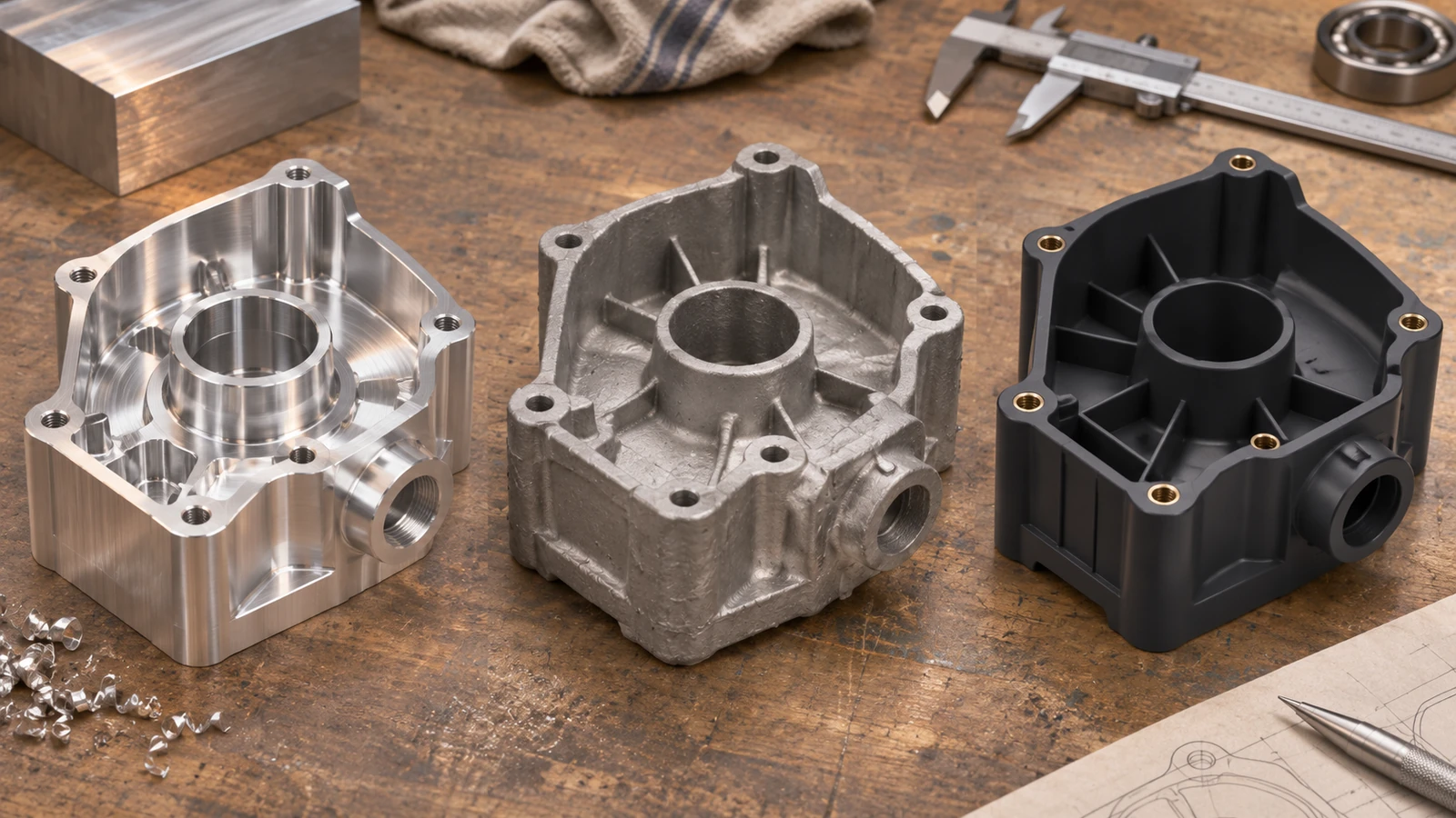
Injection molding may be relevant for polymer designs whose operating environment and material specification support it. The design must consider shrinkage, gate location, weld lines, inserts, and the interface between molded features and any secondary-machined surfaces. A molded prototype can help evaluate the actual geometry but should be interpreted in light of the prototype tooling and resin used.
| Decision factor | Questions to resolve | Process implication |
|---|---|---|
| Prototype purpose | Is the sample for fit, flow, installation, or production validation? | Choose a route that represents the feature being evaluated |
| Part geometry | Are there thin walls, complex ports, undercuts, or inserts? | Compare billet, casting, or molding access and process limits |
| Quantity and revision risk | How many samples and what design changes remain? | Balance tooling commitment against machining time and redesign cost |
When a casting route is appropriate, review the site’s die casting capability alongside the finishing operations required for the thermostat seat and mating faces. If the design remains in prototype development, the automotive prototyping page describes the broader engineering context, while CNC-Bearbeitung is relevant for the features that require cutting and dimensional verification.
Separate as-formed geometry from machined datums
In a cast or molded housing, a fixture cannot assume every surface is a reliable locator. Drafted walls, parting lines, flash, or local variation may cause rocking or force the workpiece into distortion. Use defined locating pads or previously machined references where the design allows. Clamp against robust regions and consider whether thin walls can deflect under cutting or holding forces.
A common sequence is to create stable reference features, machine the main mounting face and seat, then finish related ports and threaded features from a controlled datum scheme. The exact sequence varies with geometry. If the seat and flange must remain aligned, machining them in a common setup may reduce transfer error. If multiple setups are necessary, specify the re-location method and what inspection will verify the relationship.
Pay attention to internal radii and tool access. A tool that reaches the bottom of a cavity may not clear a narrow corner or intersecting port. The design can often be made more robust by specifying practical corner radii, accessible tool paths, and an explicit edge condition. This is especially important where a burr could interfere with a thermostat, coolant path, or seal.
Make sealing and port quality measurable
A leak at a housing interface can come from a face that is not flat, a damaged edge, an incompatible gasket, a misplaced fastener, a porosity path, or an assembly condition that compresses unevenly. Dimensional inspection can check the flange, seat, and bolt pattern. It cannot alone rule out a through-wall leak. If a pressure or leak test is required, state the medium, pressure, duration, fixture, and acceptance rule in the project documents.

Coolant ports should be checked for location, bore size, edge condition, and communication with the intended passage. If the drawing controls surface finish or sealing land roughness, inspect the specified surface after the final finishing step. Coatings or surface treatments may change fit; define masking boundaries and when dimensions are checked. Avoid promising a generic finish or leak performance without the design requirements and test evidence.
For polymer housings, the plan may also need to address insert retention, weld-line location, and dimensional change after conditioning or temperature exposure if the customer specification requires it. These are project-defined checks, not universal acceptance criteria. The engineering team should separate a prototype observation from a validated production requirement.
Choose material with the service environment in view
Material selection depends on temperature range, coolant compatibility, mechanical loading, weight, joining method, and the approved specification. Aluminum alloys, ferrous metals, and engineering polymers each bring different processing constraints. Do not choose a grade only because it machines easily or appears in another vehicle component. Confirm the exact grade, temper or condition, and any required material documentation.
A metal housing may need attention to corrosion protection and galvanic relationships at connected fittings. A polymer body may need consideration of chemical compatibility and heat exposure as defined by the application. If secondary finishing is specified, include it in the dimensional plan. The material and finish should be reviewed together because the final interface is what the assembly sees.
The site’s aluminum machining resource can support early manufacturing discussions for metal versions. For plastic variants, material pages should be selected only after the design owner confirms a polymer grade and its service requirements.
Prepare a supplier handoff that prevents assumptions
Provide a revision-controlled drawing, 3D model, material designation, quantity by phase, target process if already selected, surface finish, and inspection requirements. Identify the thermostat seat, sealing surfaces, port interfaces, and critical datums. Mark which features are as-cast or molded and which are machined. If the design is still under review, state the questions the sample must answer so that the supplier can propose an appropriate prototype route.
Ask for a DFM response that identifies tool access, fixture assumptions, stock allowances, insert or gate considerations, and finishing sequence. A complete quotation should make visible any secondary machining, finishing, or test cost rather than hiding it in a general unit price. Keep the accepted sample, drawing revision, and inspection report connected so that later changes can be traced.
FAQ
Does every thermostat housing need to be cast?
No. The route depends on the design, material, quantity, and development stage. A prototype may be machined, while a repeat part may use casting or molding followed by selected finishing.
Which surfaces are usually machined?
The drawing may call for machining on a thermostat seat, mounting flange, sealing face, ports, threads, or locating features. The exact features must come from the approved design.
Can a machined prototype prove production casting quality?
Not by itself. A billet sample can support fit and geometry checks but does not reproduce cast structure or process variation. Use a prototype route suited to the question being evaluated.
What should be specified for leak testing?
Define the test method, pressure or conditions, duration, fixture, and acceptance criteria in the customer drawing or validation plan. Do not rely on an unspecified “leak tested” statement.
The most reliable thermostat housing plan keeps the thermostat seat, ports, mounting face, material, and test evidence in one discussion. When those interfaces are defined before the process is chosen, the supplier can recommend a route that fits the prototype goal and the intended production path.