


Define the bracket function before choosing thickness
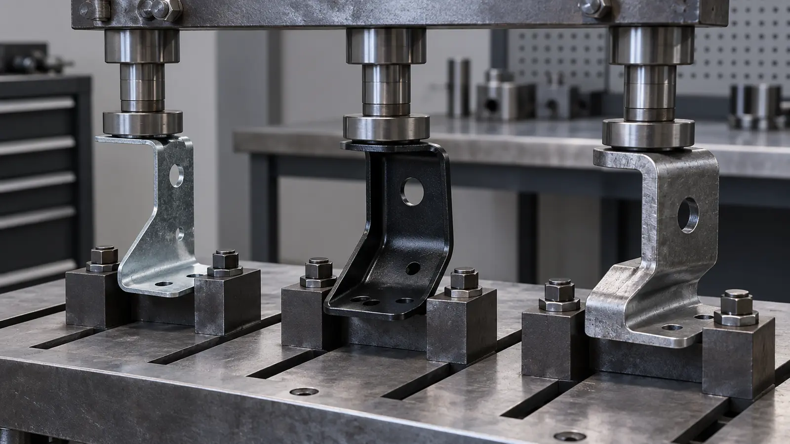
Start with load direction, vibration, temperature, clearance, mating parts, and service access. A sensor mount needs positional stability; a heat shield support needs thermal clearance; a wiring bracket needs safe edges and controlled retention. These requirements often matter more than adding material.
For early fit and interface checks, automotive rapid prototyping lets the team test the bracket inside the surrounding assembly before production tooling or fixtures are finalized.
Build the drawing around datums
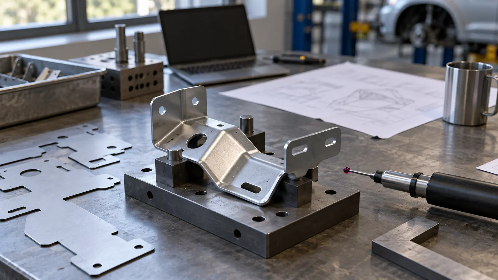
The 3D model shows shape, while the drawing defines acceptance. Identify the primary mounting face, locating holes, bend angles, flatness, weld points, and surfaces that contact other parts. Separate critical interfaces from cosmetic or nonfunctional faces.
| Drawing item | Useful control | Common risk |
|---|---|---|
| Mounting holes | Position and true position | Fastener mismatch |
| Locating face | Flatness and datum reference | Assembly tilt |
| Bend feature | Angle and inside radius | Clearance loss |
| Weld location | Joint and distortion note | Bracket movement |
Control bends, holes, and edges
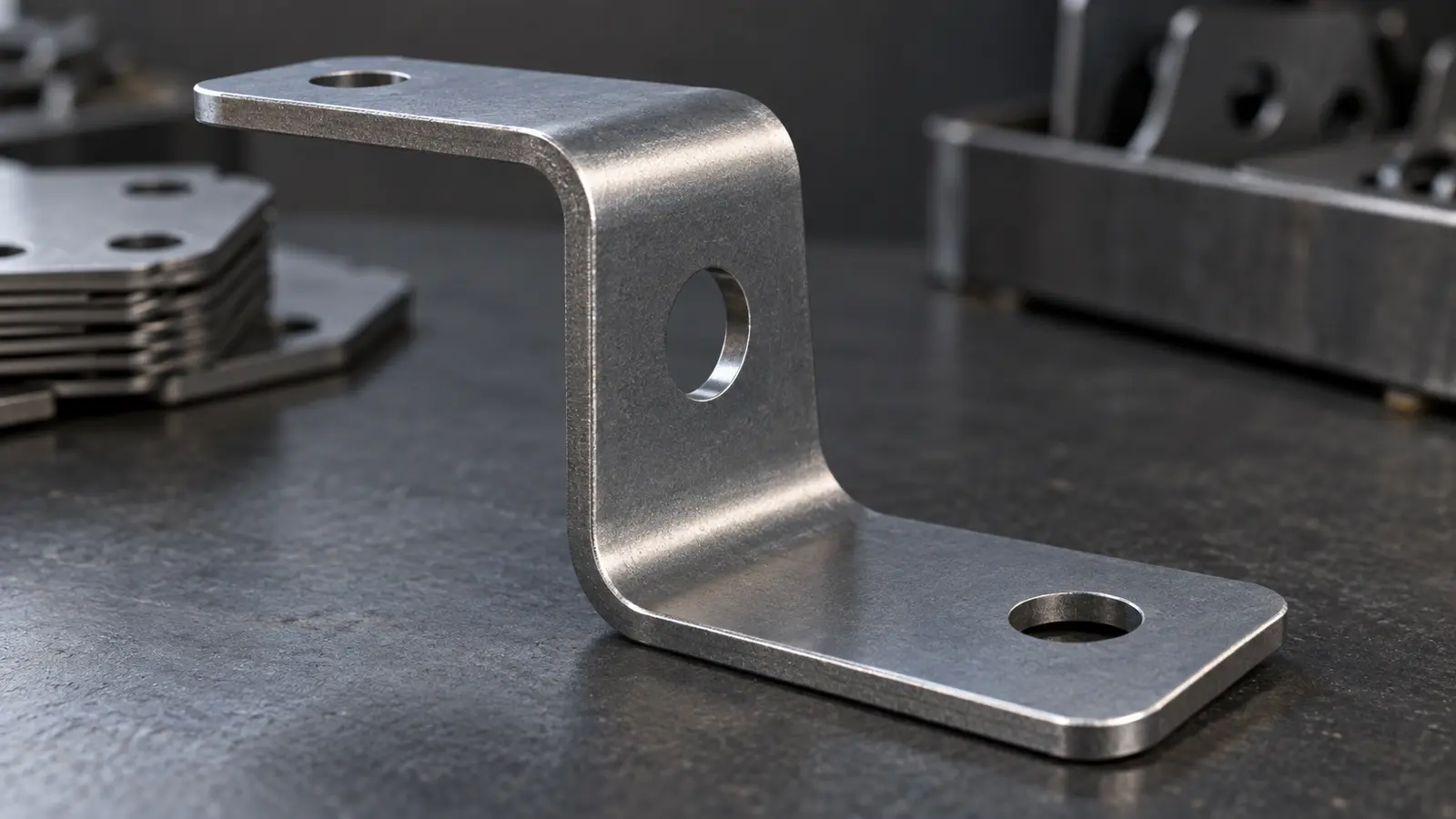
Holes placed too close to a bend can deform during forming. Tight edge distances can create tearing or leave too little material around a fastener. Long narrow flanges may spring back or twist, while sharp internal corners concentrate stress and complicate tooling.
Keep critical holes referenced to stable datums, allow realistic bend radii, deburr edges that technicians or cables may contact, and review the flat pattern together with the formed model. The sheet metal fabrication service should receive both models and the intended inspection points.
Match material and finish to exposure
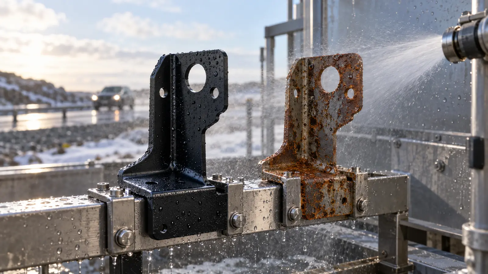
Mild steel, stainless steel, and aluminum each change stiffness, mass, corrosion behavior, bend response, and finishing options. Underbody exposure, battery-adjacent environments, heat, moisture, and galvanic contact should be considered before the material is fixed.
A coating can improve corrosion resistance but may also change hole fit, grounding, or sliding interfaces. Specify whether the finish is cosmetic, protective, electrically functional, or simply intended to remove sharp edges.
Plan the fabrication route
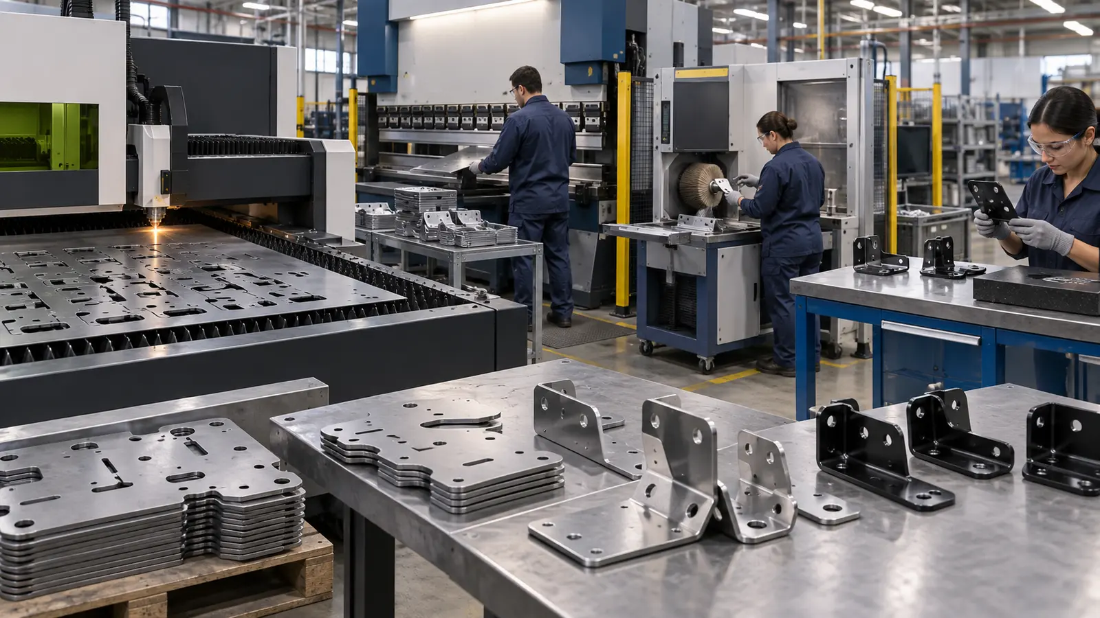
- Cut the blank by laser or another suitable method.
- Form bends using controlled tooling and a defined sequence.
- Join parts by welding, riveting, clinching, or fasteners where required.
- Remove burrs and verify critical geometry.
- Apply the agreed finish and recheck interfaces after coating.
For changing designs, flexible fabrication is often more useful than a route that assumes immediate high-volume stamping. As quantity and geometry stabilize, the process can be reevaluated.
Validate the bracket in the surrounding assembly
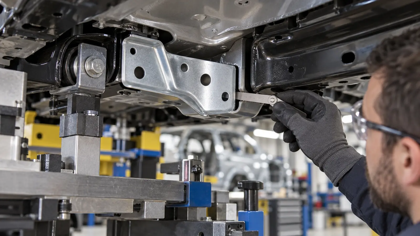
A bracket can pass a bench measurement and still fail during installation. Check tool access, cable routing, fastener engagement, weld distortion, adjacent-part clearance, and whether the operator can install it in the intended sequence. If it carries a sensor, validate position after vibration or thermal exposure where relevant.
A useful prototype review records not only whether the part fits, but also which dimension controls the fit and which manufacturing step can move it. That information makes the next revision faster and more predictable.
Häufig gestellte Fragen

What material is best for an automotive sheet metal bracket?
There is no universal choice. Load, corrosion, temperature, mass, bendability, joining, and finish requirements should determine the material.
Should holes be cut before or after bending?
Many holes are cut in the flat blank, but critical interfaces may require a secondary operation or a process review to control distortion and position.
How can bracket vibration be reduced?
Use an appropriate load path, sufficient stiffness, effective mounting, realistic tolerances, and validation in the assembled condition.
What belongs in a bracket RFQ?
Include the 3D model, drawing, material, quantity, finish, joining method, critical datums, inspection needs, and mating assembly information.
Close the loop with assembly evidence
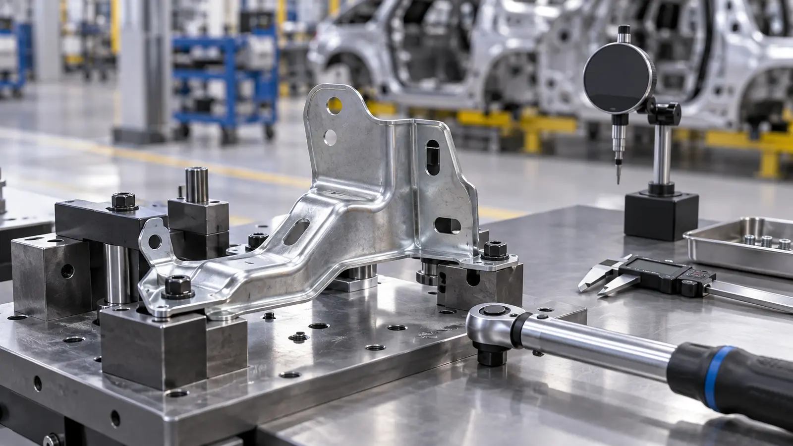
The final review should measure the bracket after forming, joining, finishing, and installation. Check hole position, bend angle, flatness, fastener engagement, cable clearance, and contact with neighboring components. If a coating changes a fit, record the finished condition rather than relying on a pre-finish measurement. This evidence helps the next revision address the real source of variation.
For a procurement request, include the 3D model, controlled drawing, material, quantity, finish, joining method, critical datums, inspection requirements, and mating assembly. Ask the supplier to identify bend assumptions, weld distortion risks, secondary operations, and the dimensions that should be checked at first article. A bracket is ready for the next stage when its function, process, and acceptance method are all clear.

