


Automotive insert molding combines a metal or non-molded feature with a polymer body in one controlled manufacturing step. The insert may provide a thread, shaft, electrical contact, locating datum, reinforcement, or wear surface. The process succeeds when the insert is treated as part of the mold, material, and final assembly—not as a loose object that happens to be surrounded by plastic.
For automotive development, insert molding can reduce secondary assembly, improve alignment, and protect a metal feature inside a molded component. It can also create new risks: insert movement, knit lines, local shrinkage, thermal mismatch, flash, incomplete encapsulation, or damage during loading. This guide explains how to design and qualify the interface.
What the insert must do
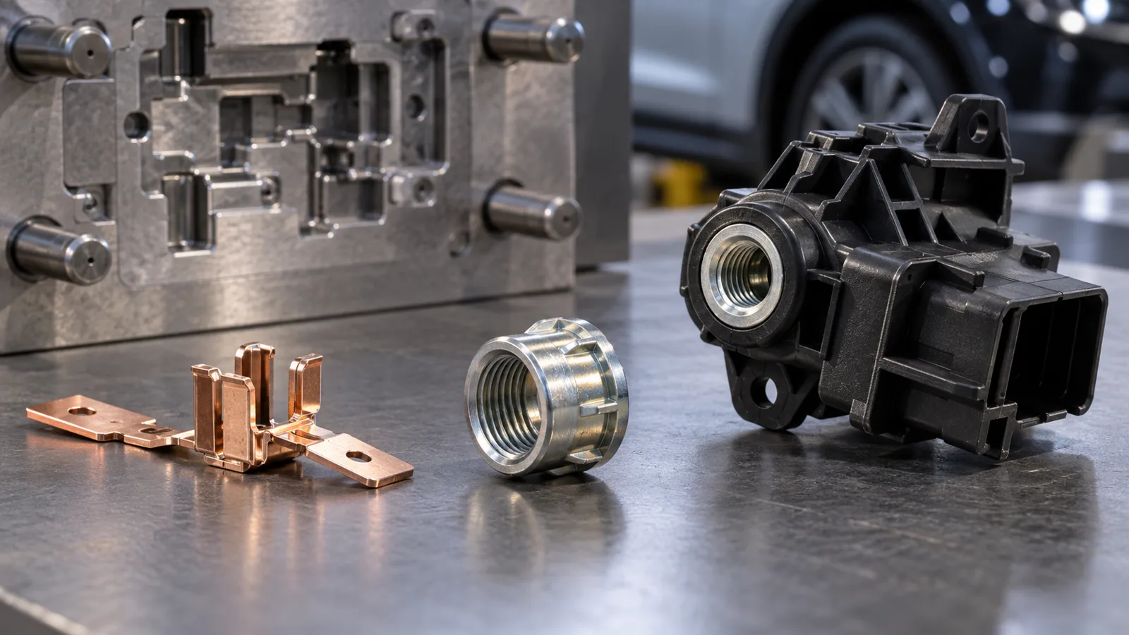
Classify the insert before selecting a process. A threaded bushing may need torque and pull-out resistance. A stamped electrical contact may need controlled exposure and insulation distance. A shaft may need concentricity and rotational retention. A bracket may carry a load through both the metal and polymer. These are different engineering problems even when the molding machine is the same.
Define load direction, temperature, chemical exposure, vibration, electrical function, service access, and the features that control alignment. If the part is an early prototype, state whether the goal is fit, handling, assembly sequence, retention, or production-material behavior. The automotive rapid prototyping workflow can test the complete interface before a dedicated mold is committed.
Design the metal-plastic interface
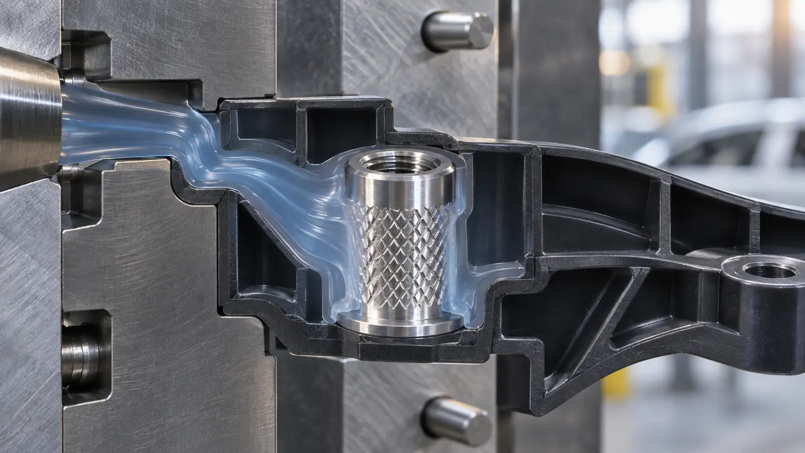
Retention can be mechanical, chemical, or both. Knurls, grooves, holes, flats, shoulders, and formed features can resist rotation or pull-out. However, a retention feature also changes the local plastic thickness and may create a sink mark, void, knit line, or stress concentration. The best geometry carries the expected load without creating a large isolated mass of polymer.
| Insert requirement | Design response | Verifizierung |
|---|---|---|
| Resistance to rotation | Flats, knurls, grooves, or anti-rotation ribs | Torque test |
| Resistance to pull-out | Engagement length and mechanical lock | Axial load test |
| Electrical continuity | Defined exposed contact and insulation distance | Continuity and dielectric checks |
| Dimensional location | Stable mold locating and datum reference | Coordinate measurement |
Keep sealing lands, precision datums, and visible surfaces away from uncontrolled weld lines when possible. Review the assembled condition, because an insert can be dimensionally correct in the molded part but still fail when a mating fastener, connector, or shaft is installed.
Build the mold around the insert
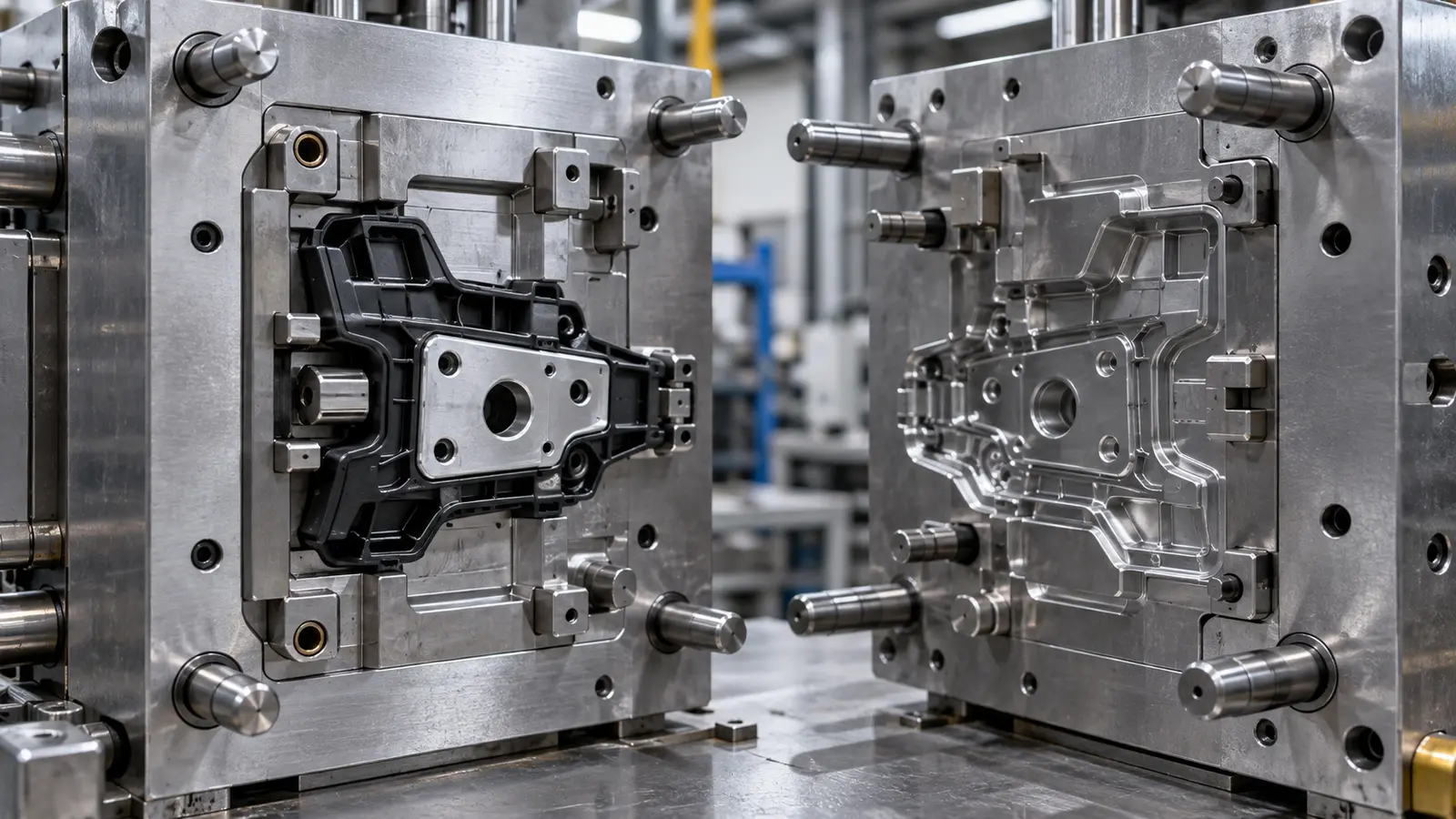
The mold must position every insert repeatably, withstand loading, permit polymer flow around the feature, and release the finished part without damaging the interface. Loading can be manual, semi-automatic, or automated. The choice depends on quantity, orientation, insert complexity, cycle time, and the cost of a misplaced feature.
Mold designers should review gates, vents, ejection, parting lines, shutoffs, insert pockets, and operator access. A gate placed directly against a delicate contact may damage the feature or leave an unacceptable mark. Poor venting can create burns or incomplete filling near the insert. Ejector force should not push against a thin plastic section that has not cooled sufficiently.
Draft and demolding direction deserve the same attention as insert retention. Undercuts can improve mechanical lock but may require slides, lifters, collapsible features, or a different assembly sequence. These choices affect tooling cost, cycle time, maintenance, and the ability to revise the design.
Control material, heat, and process conditions
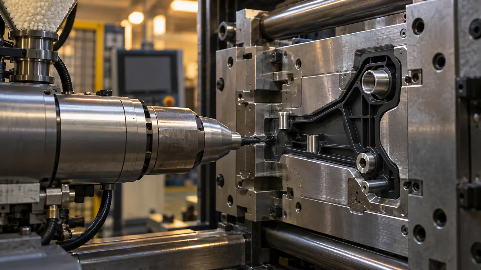
The insert and polymer expand and contract differently. That mismatch can create residual stress, gaps, cracking, or loss of retention after temperature cycling. Confirm polymer compatibility, insert coating, surface condition, melt temperature, mold temperature, drying requirements, and any preheating or cleaning step needed before loading.
Moisture in hygroscopic resins can affect appearance and mechanical performance. Contamination on the insert can weaken bonding or create voids. The process window should be established through trials, and material lots should be traceable to the approved sample. The low-volume injection molding service can support functional trials while the insert geometry and loading method are still being refined.
For a production-like review, record injection pressure, fill time, packing, cooling, insert temperature, and cycle assumptions where these values affect the result. The purpose is not to publish arbitrary machine settings; it is to make the acceptance sample reproducible.
Verify the finished part, not only the insert
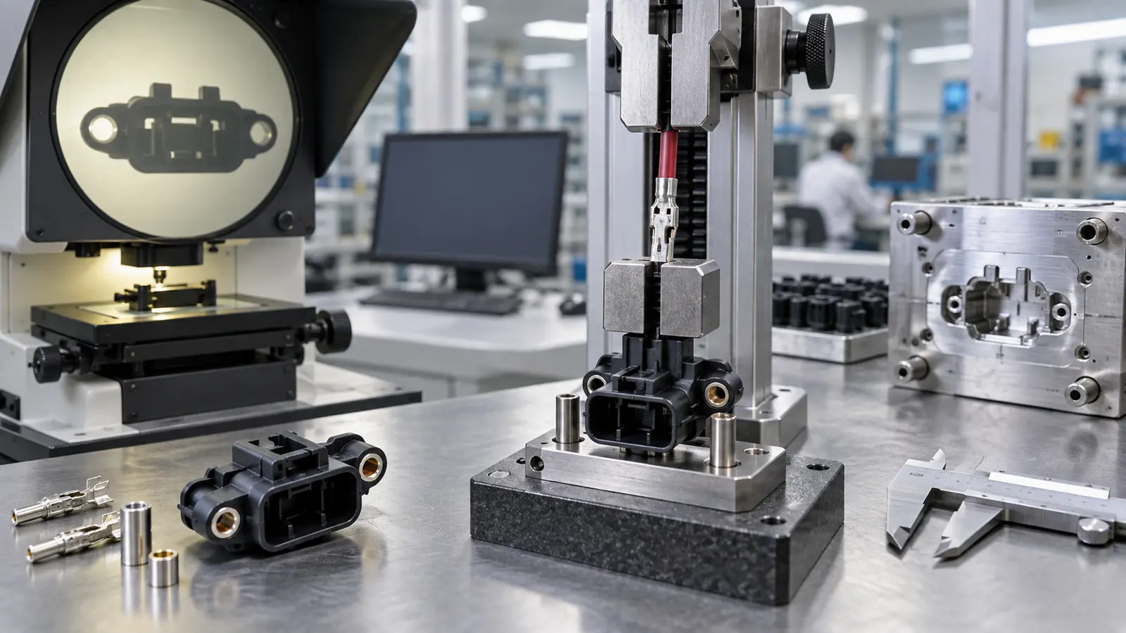
- Confirm insert material, coating, orientation, and lot identity.
- Measure insert position relative to functional datums.
- Inspect flash, short shots, sink, voids, burns, and exposed areas.
- Test torque, pull-out, electrical continuity, or movement as required.
- Repeat the check after temperature, vibration, moisture, or chemical exposure when relevant.
Inspection intensity should follow consequence of failure. A decorative insert and a safety-related mounting feature should not receive identical acceptance criteria. If an interface is hidden after assembly, define an earlier checkpoint or use an assembled functional test.
Choose the right route for the program volume
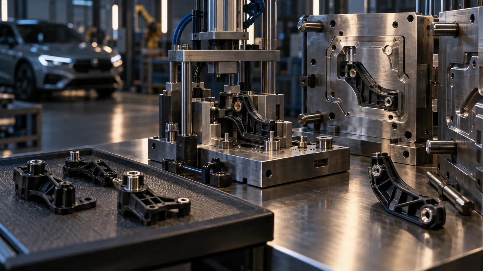
Insert molding is strongest when it removes a later assembly step and creates a stable, repeatable interface. For very small quantities or frequently changing geometry, CNC machining with separate assembly may be easier to revise. For a mature, high-volume design, dedicated tooling and controlled insert handling can reduce labor and improve consistency.
Compare the complete system cost: insert supply, loading labor, mold complexity, secondary operations, inspection, scrap, and the cost of a misplaced insert. A lower molding cycle price is not a saving if the assembly requires rework or if the interface fails during validation.
Prepare an RFQ that exposes the real risk
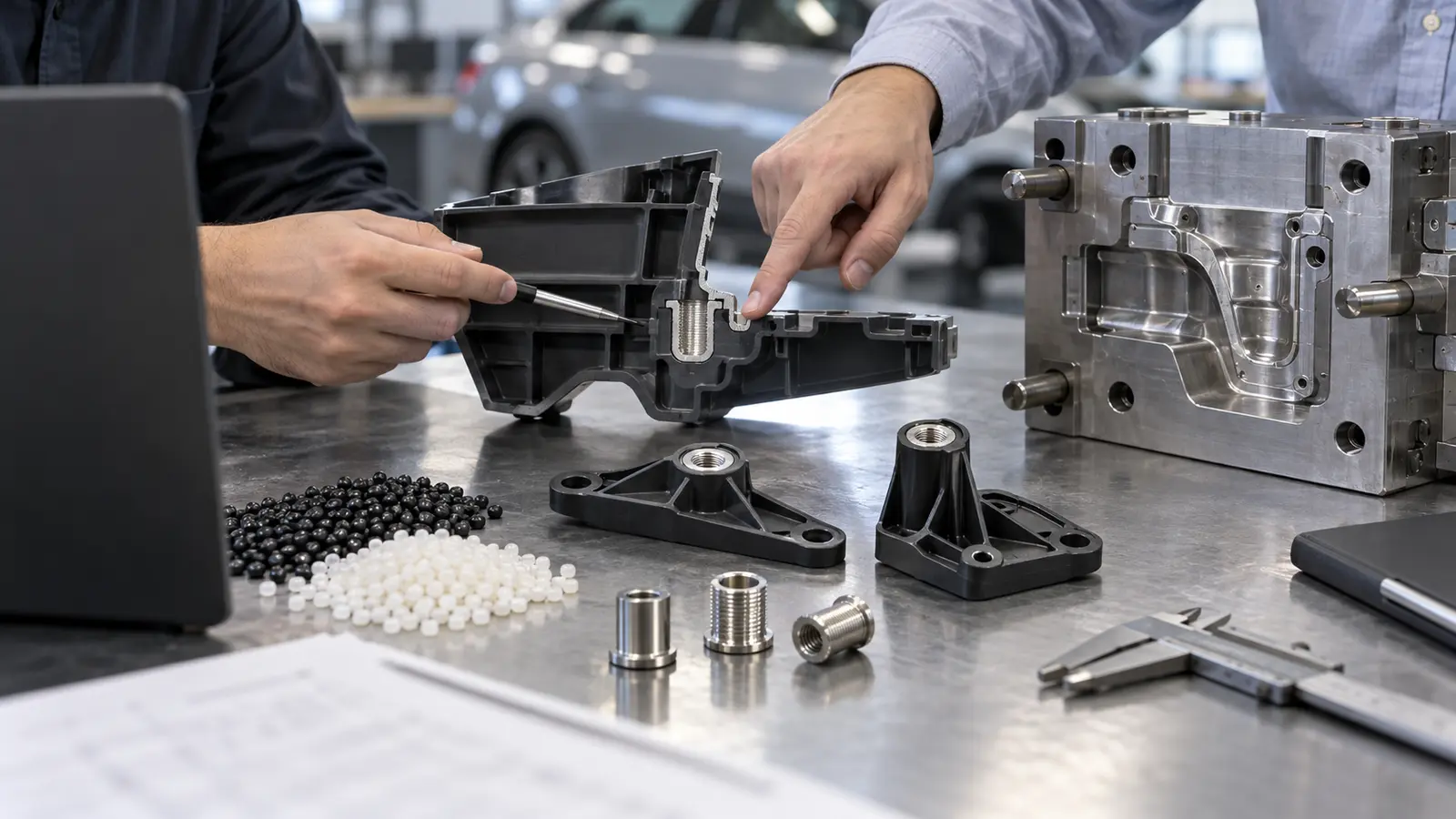
Include the carrier or insert model, molded-part model, polymer specification, insert material and coating, retention requirement, visible zones, expected quantity, temperature range, chemical exposure, and intended tests. Mark surfaces that must remain exposed and state whether the insert is supplied by the buyer.
Ask the manufacturer to propose the loading method, mold locating strategy, gate and vent approach, sample quantity, inspection checkpoints, and any changes needed for draft or mechanical retention. This encourages an engineering review before tooling rather than a correction after the first shot.
Häufig gestellte Fragen
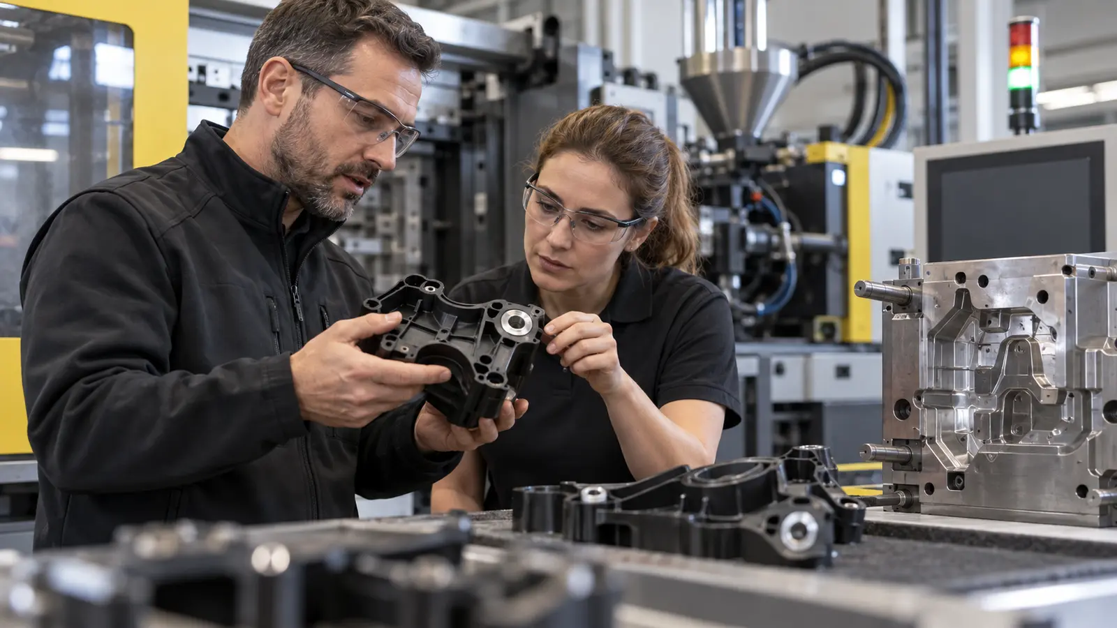
What inserts are common in automotive insert molding?
Threaded bushings, shafts, stamped contacts, reinforcing sleeves, brackets, magnets, and other metal features are common examples.
Can insert molding improve assembly reliability?
It can reduce separate fastening and alignment steps when insert location, retention, and molding conditions are controlled.
Why does an insert move during molding?
Insufficient locating, injection force, poor loading sequence, weak retention geometry, or unsuitable gate and flow conditions may contribute.
Is insert molding suitable for prototypes?
Yes, when the prototype must represent the metal-plastic interface. The mold and loading method should match the validation goal.
What should be approved before production tooling?
Approve insert specification, retention design, datums, mold concept, process window, inspection plan, and the tests that define acceptance.

