


Aerospace tooling is the collection of jigs, fixtures, forming tools and inspection aids used to make or assemble aerospace components. Choosing it starts with the operation it must control: locating a part for machining is different from supporting a panel during assembly or checking a finished contour. The lightest tool, hardest material or most expensive fixture is not automatically the right choice.
For a buyer sourcing custom tooling, the useful question is more specific: what must stay in position, under which loads, and how will the tool prove that it can repeat the job? This guide concentrates on manufacturing aids for parts and subassemblies, not purchasing CNC machines or selecting flight hardware.
Start with the job, not the tool material
Write a one-sentence duty statement before requesting a quote. For example: support an aluminum enclosure while its mounting holes are drilled, without marking the finished outside faces. That statement identifies a process, a positional requirement and a surface constraint. It is much more useful than asking for an aerospace-grade fixture, a phrase that leaves the actual acceptance conditions undefined.
A machining fixture resists cutting loads while exposing the required features. An assembly jig establishes the relationship between separate components. An inspection fixture provides a repeatable measurement setup without hiding unacceptable geometry. Although a single baseplate may support several operations, the locating logic and acceptance checks need to be specified for each use.
Place the tooling request within the planned aerospace manufacturing processes. A tool that works for rough machining may be unsuitable after coating, when contact surfaces change or the drawing requires protection of cosmetic areas. The manufacturing sequence determines which part condition the tool will see.
Define the expected production quantity, loading frequency, cleaning method and operating environment. A manually loaded development fixture has different wear and access priorities from a fixture repeatedly used across shifts. Also identify who can approve changes: the tooling supplier can propose a locator modification, but cannot silently redefine the product datum system.
A fixture that locates can still distort the part
Location and restraint are separate jobs. Locators establish position; clamps keep the component seated against those locators. If a clamp pushes on an unsupported wall, the part can move into the desired position only while the load is applied. After release, it may spring away from the shape that was machined or measured.
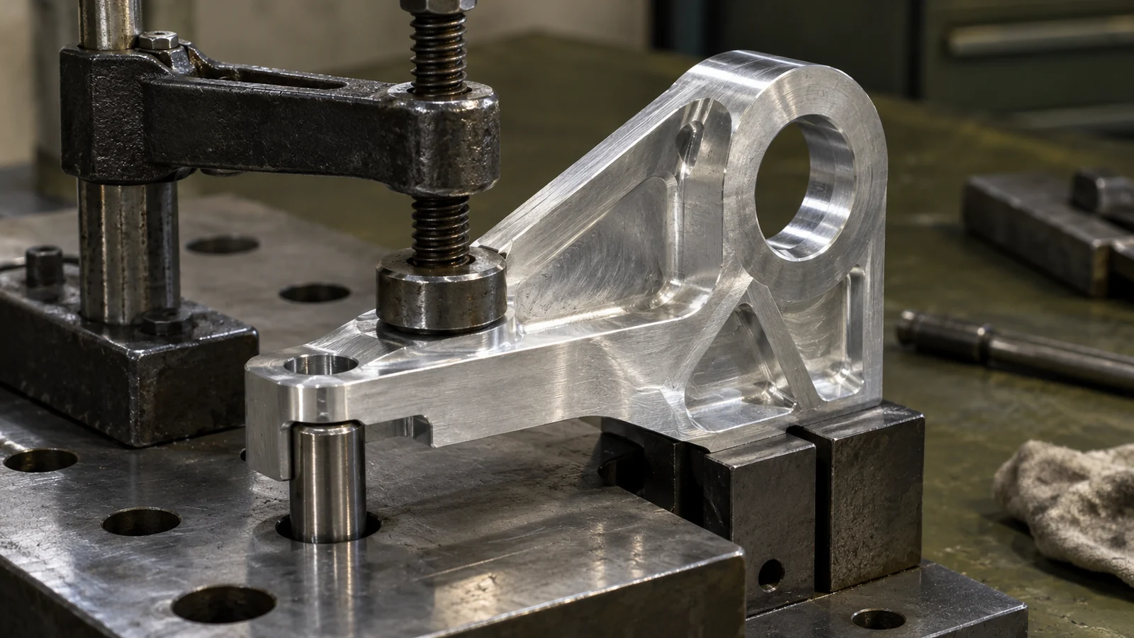
Review the force path from clamp to workpiece to support. Contact should be planned around sufficiently stiff regions, while the tool must resist the forces generated by the operation. Extra clamps do not necessarily improve control. They can overconstrain a component, obstruct access or create inconsistent seating when operators tighten them in different sequences.
A locator example worth discussing at the design review
Consider a plate positioned by two holes. Two close-fitting round pins may bind if the actual hole spacing varies within its permitted range. A locating arrangement with appropriate relief in one direction may allow seating while retaining the required positional control. The correct solution depends on the drawing and load direction; it is not permission to loosen both pins until the plate fits.
Tool-component manufacturer Carr Lane discusses material choice, weight, operator access and locating components in its aerospace tooling selection guide. Treat such guidance as a starting point for a specific fixture review, rather than a substitute for a load and tolerance assessment.
For coated or soft surfaces, contact pads may need a different material from the structural base. Replaceable pads also make wear visible and maintenance more economical. However, a soft contact material that protects appearance can deform under load; both surface protection and positional stability must be tested.
Compare build routes against the duty cycle
Separate the structural body, locating features, contact surfaces and replaceable wear items before choosing a manufacturing process. The entire fixture does not need to be made from one material. A machined base with steel pins and polymer contact pads can address different requirements without forcing a compromise into a single block.
| Build route | Useful starting application | What needs checking |
|---|---|---|
| Machined aluminum body | Portable nests and moderate-duty fixture bases | Local stiffness, threaded-joint wear, contact damage and thermal movement |
| Steel body or wear inserts | Repeated locating and concentrated contact loads | Handling weight, corrosion protection and dimensional stability after processing |
| Machined engineering polymer | Protective pads and low-load contact elements | Creep, temperature, moisture and compatibility with cleaning agents |
| Additively manufactured polymer | Complex assembly supports and development aids | Build direction, surface contact, stiffness and wear under actual use |
| Fabricated frame with machined interfaces | Larger support structures | Distortion, interface alignment, handling and the final inspection sequence |
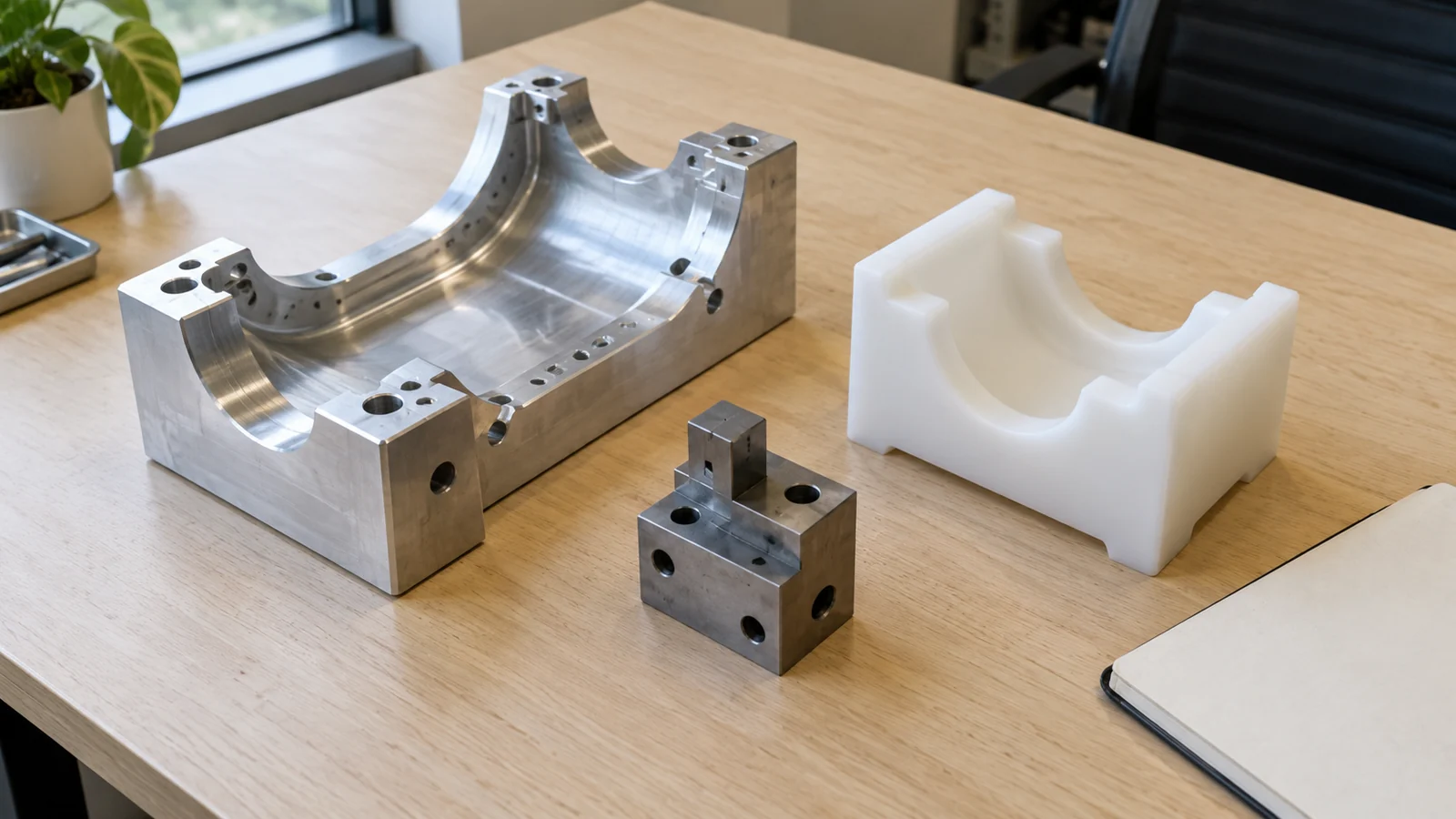
These are selection considerations, not guaranteed operating envelopes. The same material family can include grades with substantially different behavior. In particular, a printed nylon support is not equivalent to a machined nylon component simply because both are described as nylon.
Where replaceable low-friction pads are being considered, the POM machining material page provides a relevant starting point. Specify the exact grade and service conditions before approval. Avoid extending a pad material’s suitability to an entire fixture or a flight component.
A prototype can reveal loading access and assembly clearance before a durable production tool is ordered. It cannot establish long-term wear life through appearance alone. If the prototype uses another process or material, list which questions it can answer and which remain open.
Qualify the tool with more than one good part
One component seating successfully proves very little about repeatability. A practical qualification exercise reloads representative parts, follows the intended clamping sequence and checks the same controlled features after each setup. Where several people will use the tool, include more than one operator. Record variation rather than reporting only the most favorable result.
- Inspect the tool’s locating and supporting interfaces against its released drawing.
- Load representative components without forcing them into place.
- Run the intended operation or a justified simulation of its loads.
- Check the relevant features in the specified restrained or free condition.
- Repeat unloading and reloading, then examine contacts for wear or marking.
Acceptance limits must come from the project requirements and a justified allocation of the available tolerance. Do not apply a universal rule that every fixture must be a fixed multiple more accurate than the part. Measurement uncertainty, locator wear, part variation and thermal conditions all affect the usable margin.
Keep development observations distinct from qualification evidence. An engineer noticing that a clamp feels awkward is useful feedback; a recorded loading trial establishes whether the approved arrangement can actually be followed. Both belong in the review, but they answer different questions.
What belongs in the tooling handover
The deliverable should include more than the physical fixture. Request the released tooling drawing, identification and revision, loading sequence, contact and clamp locations, inspection results, replaceable-item list and agreed maintenance checks. Identify the product revisions the fixture supports so an old nest is not used automatically after a design change.
Clarify ownership of the design files and replacement parts. A buyer may own the fixture but lack the information needed to replace a damaged locator. Conversely, unrestricted modification by several suppliers can make the original inspection record irrelevant. Assign responsibility for approving, recording and requalifying changes.
When requesting custom CNC-Bearbeitung from Jucheng Precision, provide both the tooling drawing and the workpiece interface information needed to understand its function. Include quantities, loads, critical contacts and the inspection deliverable. Any specific material, tolerance or documentation commitment should be confirmed against that package.
Tooling questions before release
Can a 3D-printed fixture replace a metal one?
Sometimes, particularly for low-load supports or development checks. It is not a like-for-like substitution without considering stiffness, temperature, wear and build direction. Test the intended duty and define replacement criteria before introducing it into a controlled process.
Does aerospace tooling have to use the same alloy as the part?
No. Tooling materials serve a different function. The choice should account for dimensional stability, contact compatibility, operating conditions and handling. Thermal expansion differences can matter, but matching the alloy is not the only way to manage them.
When should the fixture be reviewed again?
Review it when the part revision, locating interface, process load, operating environment or repair changes its intended use. Also investigate deteriorating repeatability or visible contact damage. A calendar inspection alone will not catch every change that affects the tool.

