


An orthopedic impactor tip transfers a controlled blow through a contact interface, so its geometry must be considered together with the instrument body and the component it is intended to contact. A tip that fits an attachment but has the wrong face profile, seating depth, or retention relationship may not represent the intended design. The drawing and validation plan—not a generic description of an impactor—must define acceptable performance.
This article is an engineering and supplier-review guide for prototype parts. It does not provide clinical instructions, surgical technique, regulatory advice, or a claim that a machined sample is suitable for patient use. The responsible medical-device organization controls material selection, risk management, verification, cleaning, and release.
Define the instrument-to-tip interface first
Before choosing a machining plan, identify how the tip attaches to the instrument and how its contact face meets the target component. Depending on the design, the connection may use a shoulder, thread, taper, pin, or another interface. Do not infer the retention method from a rendered image; provide a released drawing and controlled model with explicit dimensions and inspection criteria.
For an orthopedic impactor tip, the functional chain can include the instrument-side connection, the tip axis, the impact face, and any feature that indexes orientation. The drawing should show how these features relate. A diameter alone may not define a fit if insertion depth, shoulder seating, rotational orientation, or face perpendicularity also matters.
Separate reusable instrument interfaces from patient-contacting or implant-contacting surfaces according to the product definition. The design owner should state which areas require particular finish, edge, cleanliness, or traceability controls. A supplier should not decide the intended clinical contact surface based solely on the shape of the part.
Use the contact face to define measurement priorities
The impact face may be flat, contoured, or otherwise shaped to match a specific design. Its profile, orientation, and position relative to the tip axis can affect whether the assembly behaves as intended. Those characteristics need drawing definitions and inspection methods that can reproduce the same reference frame.
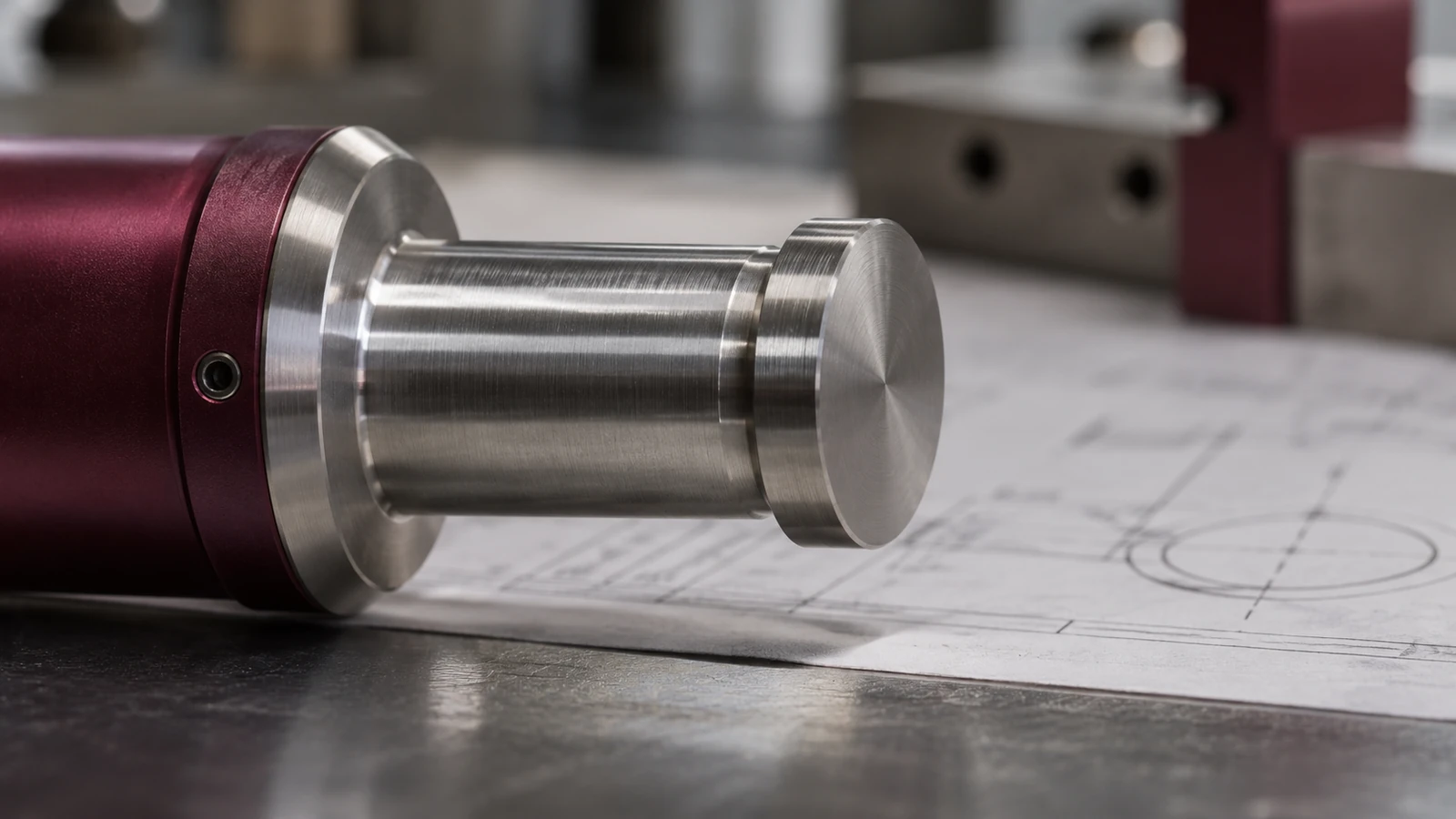
For an orthopedic impactor tip, specify the face geometry from a datum scheme tied to the attachment interface. If the tip seats against a shoulder, that shoulder may establish an axial reference. If an orientation feature aligns the face, identify the reference angle or indexing feature. Avoid applying a broad flatness or profile requirement without stating which surface, datum, and acceptance method it controls.
Edge breaks and transitions deserve explicit attention. A sharp edge, burr, or unintended corner can interfere with assembly or cleaning. Conversely, removing material from a defined contact boundary may alter the intended face. The drawing should identify controlled edges and any areas that must remain free of burrs, rather than relying on a vague instruction to deburr all edges.
Plan machining for access and repeatable orientation
CNC machining may be appropriate for a prototype when the specified material is available as stock and the geometry can be accessed with suitable tooling. A practical sequence can create a stable datum face first, establish the attachment feature, and finish the impact face relative to the same setup or a documented reference. The right sequence depends on shape, material, quantity, and required evidence.
If the tip has a contoured face, angled surfaces, or small transitions, tool access and inspection access should be considered together. A feature that is machinable but cannot be measured with an agreed method can complicate acceptance. Discuss the design model, drawing, quantity, material condition, and inspection expectations before cutting stock.
For an orthopedic impactor tip, any proposed setup or tool path is a manufacturing plan, not evidence of device validation. Changes to the geometry, material, heat treatment, coating, or finish must be approved by the responsible design authority. A prototype used for dimensional or assembly review must be labeled and controlled according to the organization’s procedures.
General material capability context is available on the site’s stainless steel machining page und titanium machining page. These pages do not establish a medical grade, biocompatibility, sterilization suitability, or device approval for a specific tip.
Material, finish, and cleaning are design inputs
Material selection must come from the controlled specification. Stainless steel and titanium alloys may appear in medical instrument designs, but the name of the component does not determine which grade or condition is appropriate. The design owner must specify the grade, mechanical condition, surface treatment, and any material documentation required for the project.
For an orthopedic impactor tip, surface finish and edge condition should be defined for the actual contact and attachment regions. A coating may change dimensions, friction, wear behavior, or cleaning considerations. If a surface is polished, passivated, coated, or otherwise treated, state whether critical features are measured before or after the operation and how the process is documented.
Cleanability and reprocessing requirements belong to the device design and validation process. A machinist can manufacture to a defined geometry and document agreed inspection results, but should not claim that a surface is cleanable, sterilizable, or safe for a clinical use without the required evidence. Material certificates and process records should be requested only as specified by the customer’s quality system.
Inspect the complete interface, not only the nominal diameter
Inspection should reproduce the drawing datum frame and verify the connection geometry, seating face, impact face, orientation, and other specified characteristics. A pin gauge or thread gauge may answer one question, but it cannot alone establish position, taper, orientation, or profile. Use a measurement method suited to each characteristic and document the setup used.
For an orthopedic impactor tip, identify which measurements confirm the instrument connection and which confirm the contact face. If a representative mating instrument or gauge is used, document its identity, condition, and the relationship it verifies. A fit check can be useful, but it should not substitute for the controlled dimensional requirements or device-level verification.
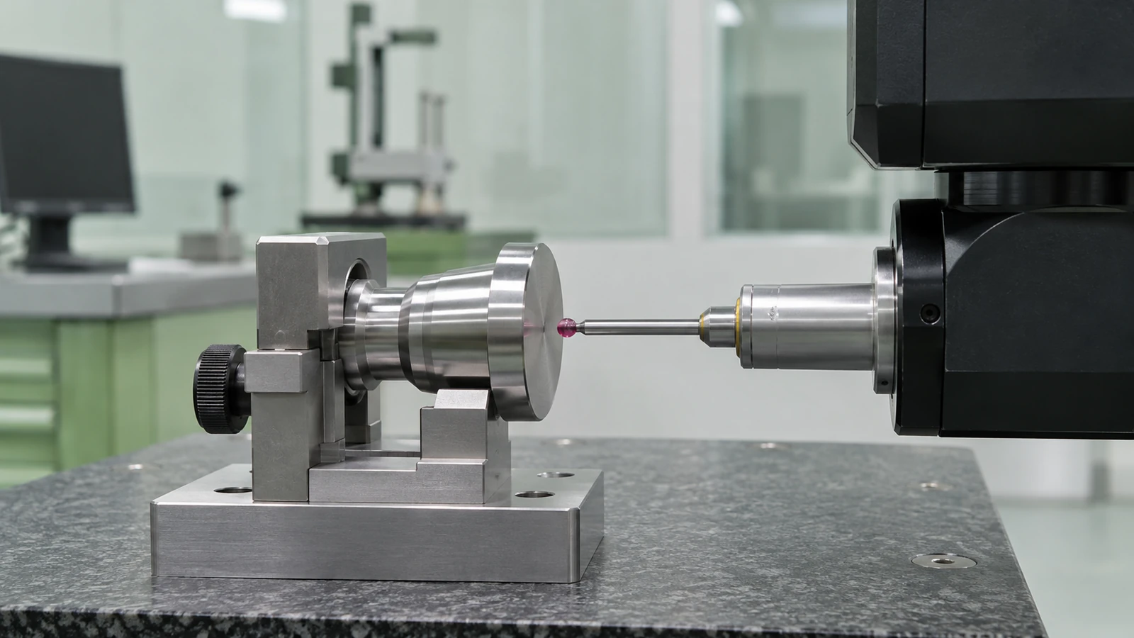
Keep the part revision, material traceability information requested, inspection records, and any approved deviations linked to the prototype. If multiple tips share a common instrument interface, define whether each tip is inspected independently and how orientation is maintained between parts. The report should distinguish measured facts from design assumptions.
Prepare a review package before making the prototype
Provide the latest controlled drawing and model, material grade and condition, quantity, interface details, finish and edge requirements, intended evaluation, and required records. Explain whether the sample is for fit, dimensional confirmation, design iteration, or another nonclinical purpose. The intended use determines which evidence is meaningful and what boundaries must be stated.
A supplier review can identify ambiguous datums, inaccessible features, unclear edge controls, and measurement risks before machining begins. It cannot replace the device manufacturer’s risk analysis, verification, clinical assessment, or regulatory decision. If the part will be used in any evaluation beyond a controlled engineering review, the responsible organization must define the applicable controls.
A well-defined orthopedic impactor tip drawing connects the instrument attachment to the contact face through measurable features. That connection makes prototype feedback more useful: the team can determine whether a fit issue comes from the interface, axial seating, orientation, face geometry, or an unresolved specification rather than making an unsupported judgment from appearance alone.
Worked interface review: the connector fits, but the impact face is off-center
Hypothetical engineering scenario, not a Jucheng customer case: a prototype tip attaches to the instrument body, but a nonclinical engineering check shows the contact face is not centered relative to the intended axis. The connector diameter passes a gauge check. That result confirms one interface only; it does not establish face position, orientation, or the complete tip-to-instrument relationship.
First identify the controlled axis and axial stop from the drawing. Measure the attachment feature and contact face in the same datum frame, then verify any indexing feature that sets rotation. If the tip was reclamped between operations, review how the setup transferred the axis. If the face is intentionally offset or angled, confirm the drawing states that design rather than treating it as a manufacturing defect.
Next distinguish geometry from an assembly mismatch. Check the mating instrument revision, seating shoulder, retention mechanism, and any approved interface component. Use a representative fixture only when its dimensions and status are documented. A qualitative contact mark can reveal a possible offset, but acceptance needs a defined measurement and cannot be inferred from an unrecorded imprint.
Close the review by assigning evidence to the right owner. Dimensional inspection can confirm specified geometry; the device manufacturer’s verification plan determines whether the assembly behaves as intended. Neither a prototype fit nor this hypothetical scenario establishes clinical suitability, sterilization performance, or patient safety.
FAQ: orthopedic impactor tip interfaces
What should the contact face be referenced to?
Reference it to the axis and seating features that control the instrument assembly, as defined by the design. The drawing should identify the datum frame and any orientation requirement. A nominal face diameter alone may not capture position or angle.
Is a successful connector fit enough to accept the tip?
No. It verifies only the connection condition that the gauge or fixture represents. The contact face, orientation, axial seating, edge condition, and other specified characteristics need their own evidence.
Can a prototype material be chosen based on machinability?
Only for a clearly limited study and with design-owner approval. A material used for fit may not represent the specified instrument material or its intended surface behavior. Record any substitution and do not claim equivalence without supporting evidence.
Does CNC inspection demonstrate medical-device compliance?
No. It can document dimensions and material information requested for the prototype. Device compliance, cleaning or sterilization validation, clinical suitability, and release remain with the responsible medical-device organization.

