


A differential side gear is defined by more than its teeth. Its spline or axle connection, thrust face, bore, and position within the differential assembly must be understood as a coordinated set of interfaces. A local dimension can be correct while the part still binds, sits at the wrong axial position, or fails to match its mating component if the drawing’s reference scheme is unclear.
This guide helps design and supplier teams review a prototype drawing and inspection plan. It is not a repair procedure, gear-design calculation, or assurance of a particular drivetrain performance. Tooth geometry, heat treatment, material condition, and acceptance limits must come from the released product definition and responsible engineering team.
Trace the side gear’s mating relationships
Start by listing what the side gear contacts or connects to: the axle or shaft interface, the opposing differential elements, the thrust surface, and any retaining or locating features. The exact arrangement depends on the design. Use the controlled assembly drawing to identify these connections rather than assuming every differential uses the same architecture.
For a differential side gear, the axle spline or other shaft connection may establish rotational engagement, while the thrust face influences axial seating. A bore, shoulder, or locating feature can also define position. The drawing should specify how these interfaces relate to the gear axis and to one another, including any controlled angular or axial relationship required for assembly.
Separate gear-tooth requirements from the machined interfaces. Tooth form, lead, profile, contact pattern, and heat-treatment effects may require specialized gear processes and inspection. General CNC milling or turning should not be represented as a replacement for a gear-manufacturing process unless the design, supplier scope, and inspection plan explicitly support it.
Choose datums that reproduce the assembled reference
A datum scheme should reflect how the part is located in the differential. The gear axis may be derived from a defined bore or spline reference, while a thrust face may set axial position. The design authority must state which features establish the reference frame and how the mating conditions are represented.
For a differential side gear, avoid dimensioning the spline, thrust face, and gear features from unrelated edges if their relative positions control assembly. A drawing can call out runout, position, perpendicularity, or profile when those controls match the function, but the tolerance and datum references must be defined. Do not assume that one concentricity note captures every relevant relationship.
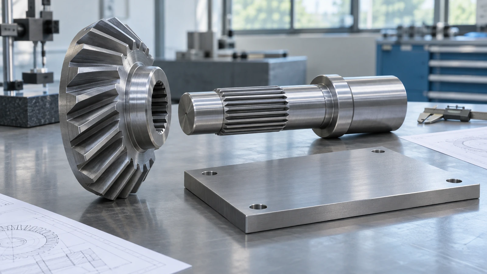
Datum simulation needs special care when the functional interface is a spline. A gauge or mandrel may represent the mating shaft, but its geometry and status should be documented. If the design uses a specific contact pattern or fit class, use the product specification; do not replace it with a nominal major diameter measurement.
Separate interface machining from gear-tooth production
Machining can establish selected bores, shoulders, end faces, slots, or other accessible features, depending on the released drawing and process plan. A stable sequence may create a reference face and axis before finishing related surfaces. If a part is heat treated between operations, the sequence must account for possible dimensional change and specify which features are finished or inspected afterward.
For a differential side gear, clarify which supplier is responsible for the teeth and which operations apply to the remaining interfaces. If gear teeth are supplied in a near-net or preprocessed condition, specify the state in which the machined datums are measured. If the same supplier performs multiple process stages, request records that preserve the part revision and operation sequence.
Tool access, clamping, and part rigidity also affect the plan. A thin rim or interrupted geometry can be difficult to support without distorting the component. Inspection should be planned alongside machining so that the chosen setup creates features that can be measured against the same datum frame. The site’s CNC machining capabilities provide general context for machined interfaces, not a claim that specialized gear cutting or tooth certification is included.
Material and heat treatment must be controlled together
Differential gears commonly involve demanding material and heat-treatment requirements, but the component name does not identify the exact grade, condition, or process. The drawing should specify material, heat treatment, hardness or case requirements when applicable, and the stage at which those characteristics are verified. A prototype material selected for easy machining may not represent the intended component.
For a differential side gear, resolve whether critical interfaces are machined before or after heat treatment, and identify which dimensions may change during the process. Any allowance for finishing must be defined by engineering. Material substitutions, hardness targets, case depth, or surface treatment must not be inferred from a generic alloy-steel label.
The site’s alloy steel machining information can help frame a manufacturing discussion, while material and thermal requirements remain controlled by the drawing and customer specification. If certification, traceability, or process documentation is required, list each deliverable clearly rather than assuming it is included.
Inspect the spline, thrust face, and axis as a system
Inspection should verify the characteristics called out on the drawing using methods appropriate to each one. A spline gauge can assess a specified spline condition, but it may not establish the position of the thrust face or the relationship of the spline axis to another datum. A coordinate measuring machine, dedicated fixture, gear inspection equipment, or other method may be needed depending on the requirement.
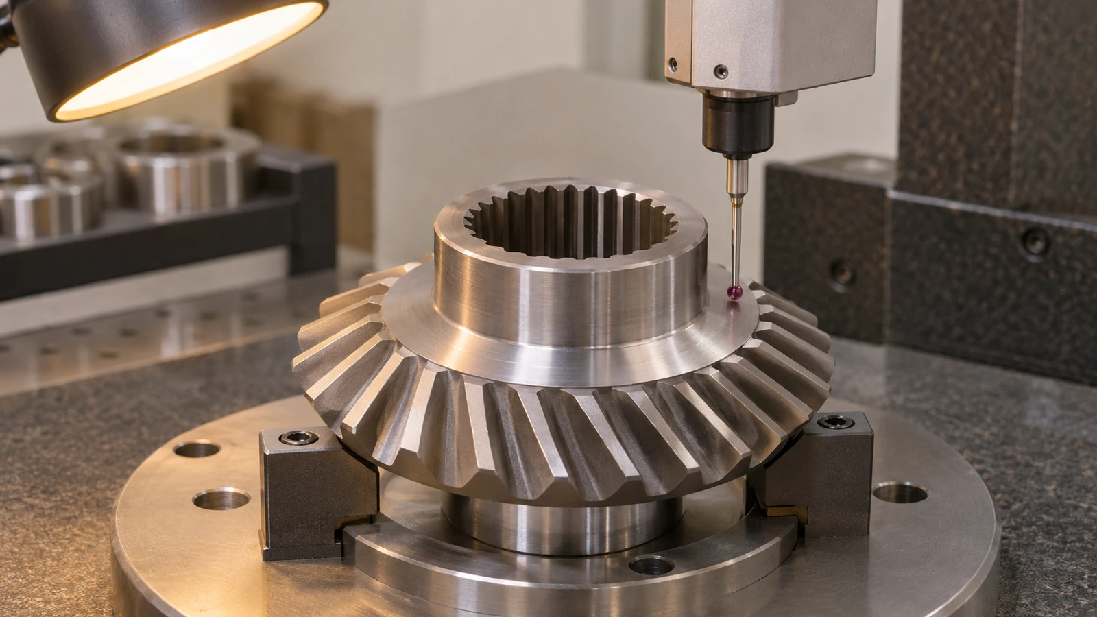
For a differential side gear, the report should state how the axis was established, how the thrust face was measured, and whether the spline was checked with a functional gauge or analytical method. If a gauge is used, identify its specification and what acceptance decision it supports. A pass/fail fit check alone may not provide the geometric data needed to diagnose a position or runout issue.
Keep tooth inspection separate from interface measurements when the procedures differ. Record the revision, material condition, heat-treatment stage, equipment, setup, and approved deviations. This allows the engineering team to trace whether a mismatch arose in the datum plan, machining sequence, treatment, gear process, or measurement method.
Questions to settle before a prototype or supplier quote
Provide the controlled part and assembly drawings, model, material and heat-treatment specification, quantity, gear-tooth responsibility, critical interface characteristics, inspection requirements, and expected documentation. Identify whether the sample is for packaging, fit, dimensional review, or a controlled test. Clarify whether the prototype must be representative of a production process or only of selected geometry.
Ask the supplier to flag ambiguous datums, features that require specialist gear processes, inaccessible inspection points, and possible distortion between operations. Agree on the measurement frame and deliverables before cutting or treating the part. That discussion can prevent a quote from assuming a process or acceptance method that the design team did not intend.
A useful differential side gear review keeps the tooth system and machined interfaces connected but distinct. When the spline, thrust face, axis, material state, and inspection method are all explicitly defined, prototype results can answer a specific engineering question without overstating what a single machined part proves about a complete differential.
Worked inspection scenario: the spline gauge passes, but axial seating is wrong
Hypothetical engineering scenario, not a Jucheng customer case: a side gear slides onto a spline mandrel and passes the specified spline gauge, yet the assembled stack does not reach its intended axial position. The gauge result is not necessarily contradictory. It answers a spline acceptance question; it may say nothing about the thrust face, gear axis, or relationship between those features.
Recreate the design’s datum frame and separate the checks. Confirm the spline condition with the specified gauge or analytical method, then measure the thrust face relative to the defined axis and axial datum. Check whether the face was finished before or after heat treatment and whether the inspection method used the correct revision and part condition. If the design contains a locating shoulder, include it in the relationship rather than inferring position from tooth contact.
Then examine the operation boundary. Determine who owns gear-tooth generation, heat treatment, and final machining of the thrust or bore features. A supplier may be responsible for only selected machined interfaces. Record the incoming state and the measurement stage so the team can distinguish a tooth-process issue from a datum-transfer or post-treatment change.
The design team should decide whether the axial stack is controlled by the thrust face, a separate shoulder, or a mating differential component. If the drawing does not make that relationship measurable, revise it before tightening the spline tolerance. The result should be a specific acceptance plan, not an assumption that a passing gauge proves the assembled differential is correct.
FAQ: differential side gear spline and thrust face
Does a passing spline gauge verify the gear axis?
Not automatically. A gauge evaluates the characteristics it was designed to represent. Axis location, runout, thrust-face position, and relationships to other datums may require separate controls and measurements.
Why should heat-treatment stage appear in the inspection plan?
Because the drawing may require features to be checked before or after treatment, and the specified process can affect dimensions. The responsible specification must identify the stage, material condition, and acceptance evidence; do not assume the finishing sequence.
Should a general CNC machining supplier be assumed to cut the gear teeth?
No. Gear-tooth generation and inspection may require a separate process and defined capability. Confirm scope explicitly and keep tooth requirements distinct from bores, shoulders, and thrust faces that may be machined under a different plan.
What documents help diagnose an axial seating issue?
Use the released part and assembly drawings, spline specification, datum scheme, heat-treatment requirements, inspection setup, and mating-part revision. The records should show what each gauge or measurement actually verified.

