


An orthopedic drill guide combines a locating surface with one or more guided features. The guide may reference anatomy, a fixture, a model, or another assembly element, depending on the device design. A guide bore can be machined to its nominal diameter and still fail to locate as intended if its axis, spacing, or orientation is not controlled from the same reference that defines the contact surface. For a manufacturing team, the useful starting point is therefore the interface chain—not the bore size in isolation.
This article covers orthopedic drill guide machining and related prototype manufacturing from an engineering handoff perspective. It focuses on how drawings, materials, workholding, and inspection affect a custom component. It does not provide surgical instructions or recommend clinical use. Design validation, intended use, regulatory controls, and acceptance criteria remain with the device manufacturer and responsible authorities.
Contents
- Define what the guide locates against
- Separate guided features from surrounding geometry
- Select material and manufacturing route by use case
- Plan machining around the guide axis
- Build inspection around the reference surface
- Document cleaning, traceability, and scope
- Frequently asked questions
Define what the guide locates against
The word “guide” is not a datum scheme. Begin by identifying the actual locating interface in the controlled product definition. It may be a contoured contact surface, a flat face, a set of pads, a fixture interface, or an assembly relationship. Determine whether the component is expected to rest on one surface, seat against multiple contacts, or be clamped in a defined configuration. The manufacturing drawing should state which features establish location and which merely provide clearance or handling geometry.
Next, connect the guide axis or axes to that reference. If several bores are present, define their spacing, orientation, and relationship to a common datum. If a bushing or insert is used, define whether it is press-fit, bonded, threaded, replaceable, or supplied as a separate component. The supplier should not infer a fit from the appearance of a section view. State the assembly sequence and the post-assembly characteristics that must be checked.
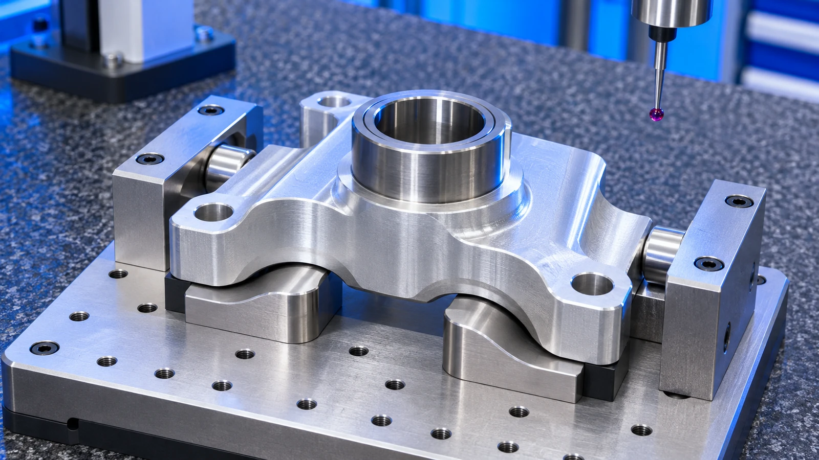
For prototypes, identify what the model is intended to confirm: packaging, access, alignment to a fixture, or a particular engineering interface. A prototype that fits a bench fixture does not automatically validate its interaction with anatomy or a clinical workflow. Keeping the test objective explicit protects both the engineering conclusion and the manufacturing quote.
Separate guided features from surrounding geometry
Guide bores, bushing seats, datum pads, clamping faces, windows, and reliefs can serve different purposes. A guide bore may need a specified size and axis. A locating surface may need a defined profile or contact condition. A clearance opening may only need to avoid interference. The drawing should distinguish these roles so inspection effort is concentrated where it supports function.
Consider the full stack: reference surface, bore axis, bushing or guide insert, and any mating fixture. A local bore measurement may confirm diameter while missing angular misalignment relative to the locating contour. A profile check may confirm surface form but not demonstrate the assembled location of a separate insert. Decide whether acceptance is based on individual features, an assembled condition, or a functional gauge, and document that choice.
Geometry can also limit tool and probe access. Deep bores, angled passages, thin walls, and tight internal corners may require a planned setup sequence. Section views and clear datum targets help a supplier assess whether the part can be clamped without deforming it or blocking critical surfaces. If the contour is derived from a scan or a digital anatomical model, identify the controlled source and revision rather than assuming that a tessellated file is the acceptance definition.
Select material and manufacturing route by use case
Drill guides can be designed in different materials and process routes depending on whether the part is a development model, a reusable instrument component, a disposable device element, or a fixture. A machined metal guide may suit certain rigid interfaces; engineering polymers can be relevant for other designs; additive manufacturing may support complex geometry or fast iteration. These are route categories, not recommendations. The device specification must define material, product form, approved processing, and any biocompatibility or sterilization-related requirements.
A CNC-machined prototype can provide crisp datums, bores, and mating faces for a fit review. A printed model can help examine a complex contour or assembly envelope before committing to a final route. The two may answer different questions and may not be interchangeable in stiffness, surface, dimensional stability, or material behavior. If a bushing is inserted into a polymer body, the joint design and inspection plan need to address how the insert is located and retained.
Material requirements should include the exact grade, condition, source controls, and records specified by the program. Do not substitute a generic “medical grade” label for a controlled specification. For broader context, the site’s medical device materials overview discusses selection considerations; the device owner must still validate the material for its intended use and processing history.
Plan machining around the guide axis
A machining plan should preserve the relation between the locating interface and the guided axis. One sequence may create reference faces first, then machine the bore or bushing seat from those datums. Another may rough the external contour, leave finishing allowance, and complete the axis features after the part has stabilized. The best route depends on geometry, material, blank condition, and access. It should be evaluated from the actual drawing rather than selected from a generic checklist.
Thin sections and contoured bodies can be sensitive to clamping. Excessive clamp force may distort a polymer or thin metal feature; insufficient support may allow vibration or movement during cutting. Fixtures should support the component near cutting loads while allowing access to the locating surfaces and bores. If a setup must be changed, use deliberate transfer references and re-establish them in a documented way.
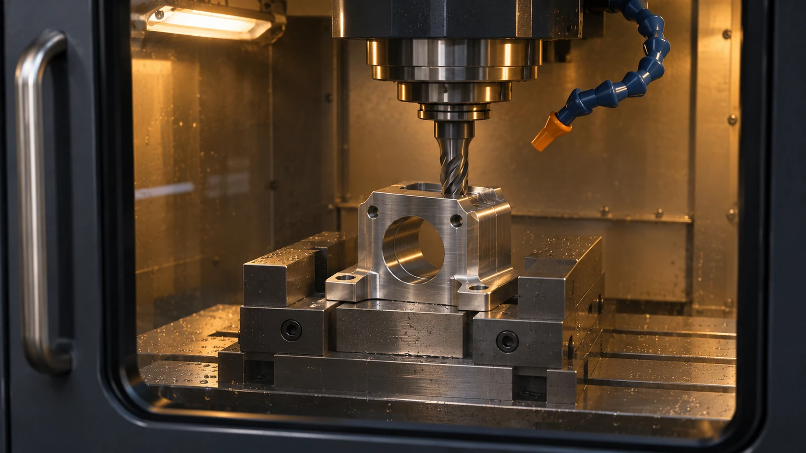
Deburring deserves specific attention around guided bores and cross-holes. A burr can obstruct an insert, alter a seating face, or create a cleanliness concern. Specify allowed edge condition and identify areas where a break edge must not change a functional surface. The CNC machining services page provides the general process context for custom components; the part drawing defines the guide’s required geometry and acceptance.
Build inspection around the reference surface
Inspection should reproduce the datum frame used to define the component. A coordinate measurement can relate the guide axis to a contour or set of pads when the measurement setup is specified. A functional fixture can assess seating and alignment in a representative assembly, but it only verifies the characteristics built into that fixture. Neither method automatically establishes clinical performance or regulatory compliance.
For multiple bores, report position and orientation relative to the same reference rather than presenting a list of isolated diameters. For a separate bushing, state whether measurements are taken before or after installation. If the part is flexible, define free-state or restrained measurement conditions. If surface scanning is used, document alignment, filtering, and the controlled model revision so a result can be reproduced.
Identify the inspection stage relative to any finishing or cleaning process. Coating, polishing, or insert assembly can change a critical interface. If a bore must be protected during finishing, identify the masking or post-process check expected. The program owner determines which characteristics are critical and what report is sufficient for a prototype or production release.
Document cleaning, traceability, and scope
Send a supplier the controlled drawing and model, revision, material specification, quantity, finish, insert details, critical characteristics, inspection report expectations, and the intended prototype question. When cleaning, passivation, coating, or sterilization-related processing is in scope, identify the approved process owner and records. A machining quote should not be assumed to include validation of those downstream operations.
State the boundary between part manufacturing and device-system responsibility. The supplier may machine a component to a released definition, while the device manufacturer owns design validation, process validation, intended-use evidence, and applicable regulatory documentation. This boundary is especially important when a prototype is used to evaluate fit or handling: say which conclusion the build can support and which decisions remain open.
For precision medical components, Jucheng’s medical precision components overview is a relevant starting point for discussing custom-part scope. Confirm the actual material, route, inspection records, and any secondary process requirements for the specific drawing.
Frequently asked questions
What should the drawing define for a drill guide bore?
At minimum, the controlled definition should identify the bore’s size and its relationship to the guide’s locating datum frame. If a bushing or insert is used, also define the fit, assembly state, and inspection stage.
Can a printed drill guide model replace a machined prototype?
It depends on the question being evaluated. A printed model may support envelope or contour review, while a machined part may be selected for a different interface or material question. The device team should state the required material behavior and verification objective.
Does dimensional inspection establish suitability for clinical use?
No. Dimensional inspection verifies specified characteristics. Clinical suitability and regulatory acceptance require separate design and process evidence under the device manufacturer’s responsibility.
A manufacturable drill guide starts with an unambiguous reference surface, a controlled relationship to each guided axis, and a declared verification plan. That gives engineering, procurement, and the supplier a shared basis for developing the component without turning a machining discussion into an unsupported clinical claim.

