


Fuel cell bipolar plates look simple from a distance: thin plates carrying repeated flow channels. In production, however, they combine delicate geometry, large functional area, demanding flatness, sealing interfaces, low-defect expectations, and materials that behave very differently under a cutting tool.
The central challenge in bipolar plate machining is not creating one attractive channel. It is keeping channel depth, land width, flatness, sealing features, surface condition, and part cleanliness consistent across the entire active area and across the required quantity.
Six Features Control Whether a Plate Works
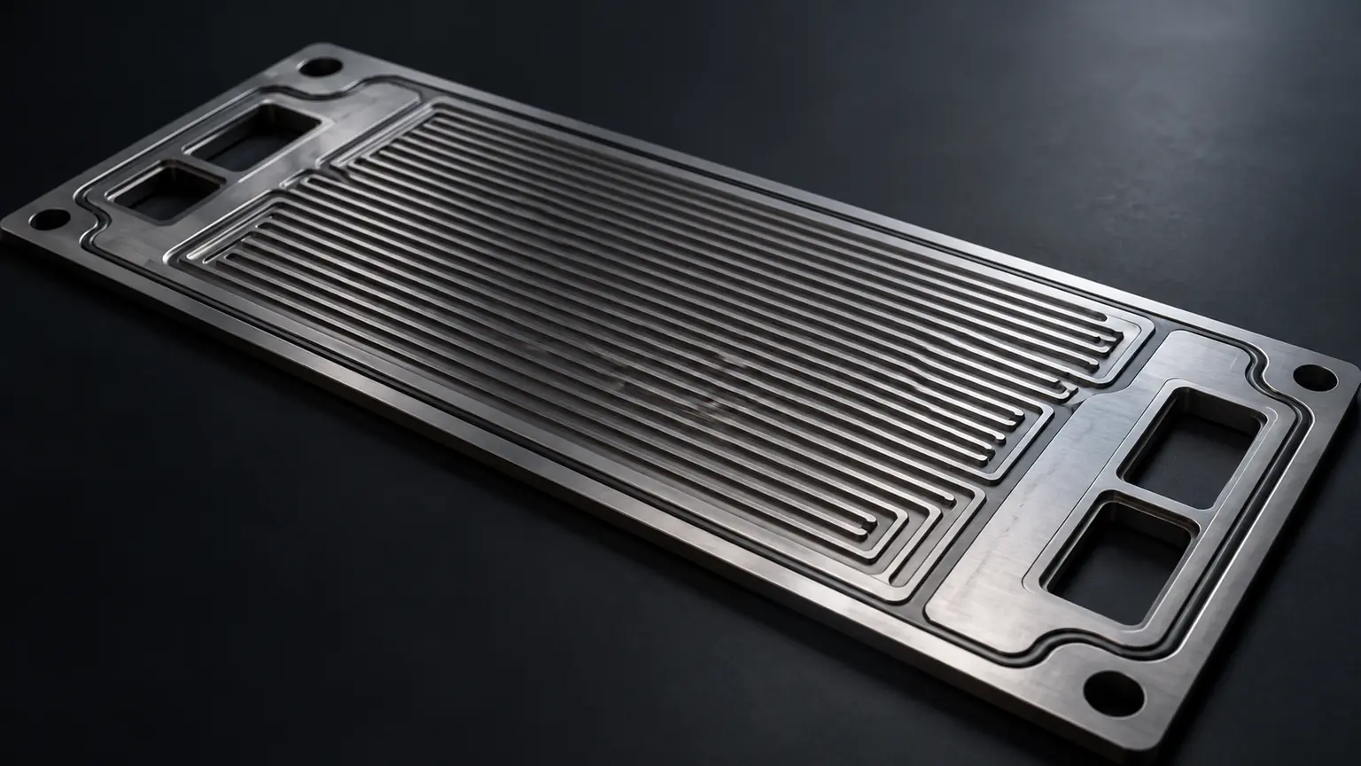
- Flow-channel geometry controls gas and coolant distribution.
- Land dimensions influence contact and local compression.
- Plate flatness affects sealing and stack load distribution.
- Sealing grooves and boundaries must remain continuous and correctly positioned.
- Surface condition influences contact, coating, corrosion behavior, and leakage paths.
- Reinheit prevents chips, dust, oils, and residues from entering the stack.
These features are linked. More clamping force can improve workholding while distorting a thin blank. Aggressive cutting can reduce cycle time while raising burrs, chipping graphite, or releasing residual stress. A process window must balance geometry, damage, and repeatability.
The Material Changes the Entire Process Plan
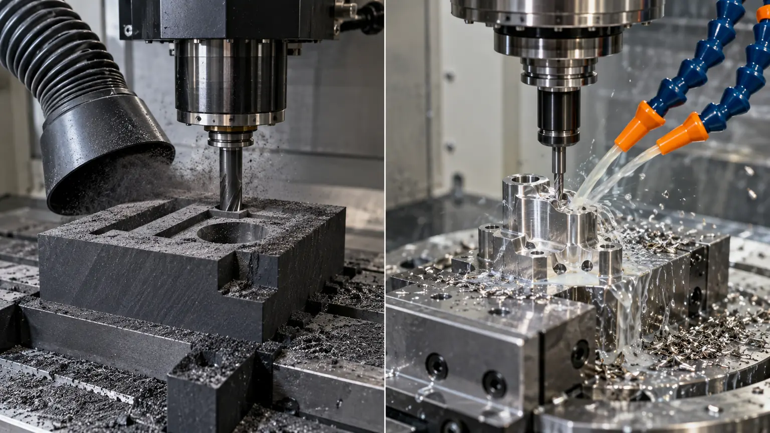
| Material family | Machining concern | Process implication |
|---|---|---|
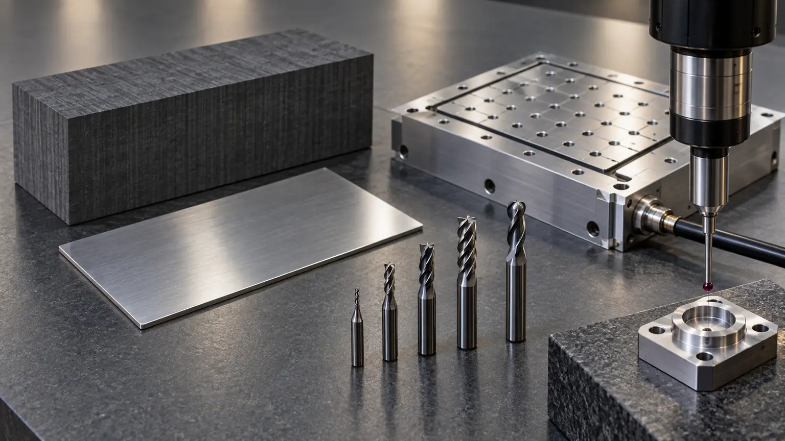
| Graphite | Brittleness, edge chipping, abrasive dust | Sharp tools, controlled engagement, extraction and cleaning |
| Graphite composite | Anisotropy and filler-dependent wear | Material-specific trials and stable tool-life limits |
| Edelstahl | Work hardening, burrs, thin-wall distortion | Rigid setup, controlled heat, careful deburring |
| Titan | Heat concentration and tool wear | Conservative cutting data and secure chip evacuation |
| Aluminum for development hardware | Burr formation and surface damage | Sharp geometry and protected handling |
Do not transfer cutting data from one plate material to another. Even within one family, grade, density, resin content, rolling condition, heat treatment, coating allowance, and blank thickness can change the result.
For metallic development plates and fixtures, precision CNC machining offers flexible channel and port changes without committing to production tooling.
Workholding Must Restrain the Part Without Rewriting Its Shape
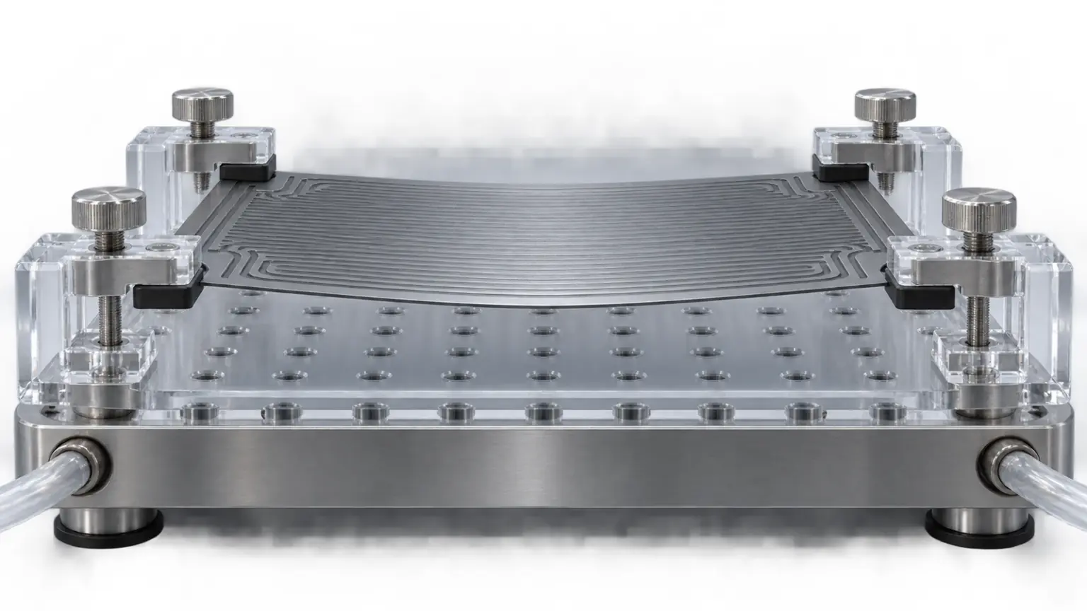
A thin plate can conform to a fixture during machining and spring into a different shape after release. Point clamps may create local dimples; vacuum fixtures may leak across channels; adhesive systems may contaminate surfaces or introduce removal stress. The fixture should support the functional area, distribute load, and provide repeatable datums.
Separate the locating job from the clamping job
Locators establish position; clamps keep the plate seated. If a clamp also forces the blank against an incorrect datum, measured accuracy may represent the fixture rather than the free-state part. The inspection plan should define whether flatness is checked restrained or unrestrained.
Plan the machining sequence around stress
Face preparation, roughing, channel cutting, sealing features, through-holes, and final surfacing should be sequenced to limit stress release and protect finished areas. A symmetric or staged removal strategy may be useful when both sides contain geometry.
Thousands of Small Tool Engagements Become a Large Error
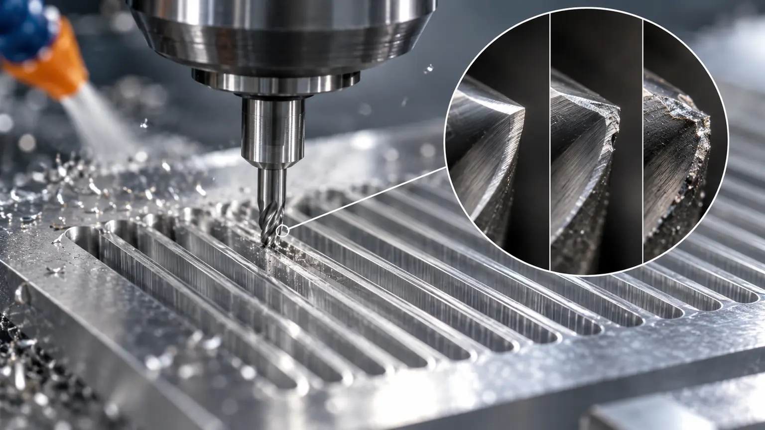
Repeated narrow channels amplify tool runout, wear, chip packing, spindle thermal drift, and programming errors. One worn tool can change channel width or leave a surface condition that affects flow. Tool-life control should therefore be based on measured feature performance, not only catastrophic breakage.
Corner radii must match both flow requirements and available cutter geometry. Very small internal radii increase tool fragility and cycle time. Where the design allows, slightly larger radii and consistent channel families improve manufacturability without changing the plate’s purpose.
Burr control is critical on metal plates. Manual deburring can round lands, alter narrow passages, and damage sealing zones. Define an acceptable edge condition and validate a repeatable deburring method before scaling. If coatings follow machining, coordinate edge condition and surface preparation with the selected surface finishing process.
Inspection Must See Both Local Features and the Whole Plate
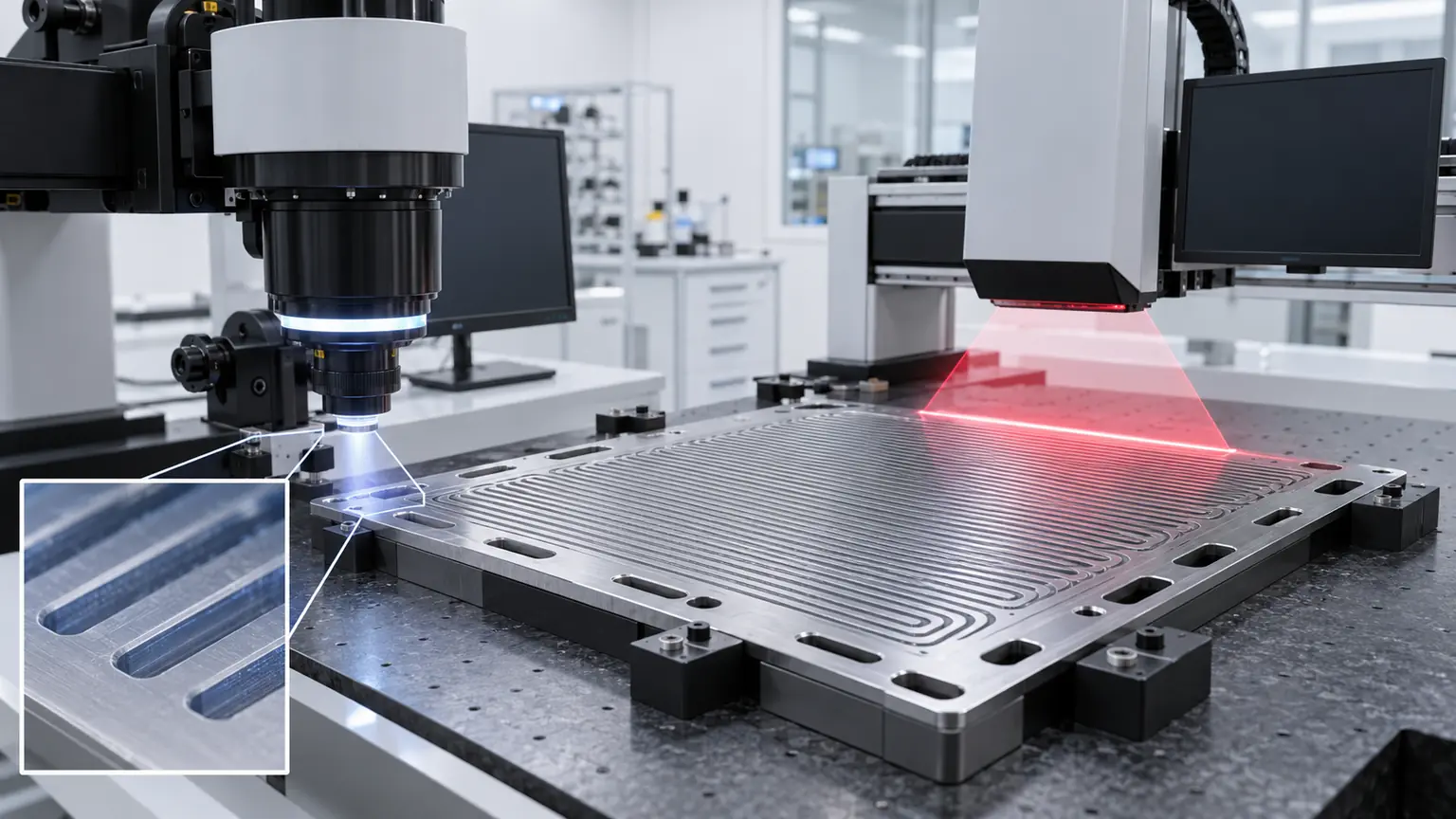
A single dimensional report cannot describe a full flow field. Build an inspection strategy with critical locations: inlet and outlet transitions, center and edge channels, sealing boundaries, manifold ports, overall thickness, and flatness. Optical measurement may be efficient for dense channel patterns, while contact methods can verify selected datums and depths.
Measurement uncertainty should be appropriate to the tolerance. The part must be clean and supported consistently. Dust or a trapped chip under a thin plate can create a false flatness result larger than the feature being evaluated.
Cleanliness is a controlled manufacturing step
Graphite dust, metal chips, coolant, fingerprints, polishing media, and packaging fibers can compromise later assembly. Specify cleaning method, acceptable residue, drying, protected handling, and packaging. Visual cleanliness alone may not be enough for a critical stack component.
Use Prototype Plates to Retire the Right Risks
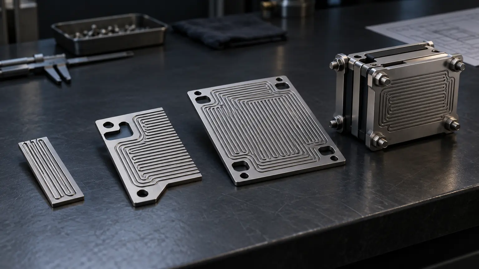
Early plates may be used for flow visualization, sealing trials, stack compression studies, coating development, or system fit. Those are different questions and may not require identical materials or tolerances. State the purpose of each build so the manufacturer does not spend production-level effort on nonfunctional surfaces.
A sensible progression is: machine a simplified flow-field coupon, then a full-size single plate, then a matched plate pair, and finally a controlled pilot batch. Jucheng Precision’s Rapid-Prototyping-Service can support the surrounding end plates, manifolds, housings, and fixtures as the bipolar plate design evolves.
Before pilot production, freeze the material source, datum scheme, tool-life rule, deburring method, cleaning route, inspection sampling, and packaging. Repeatability comes from controlling this chain, not from tightening every drawing dimension.
Fuel Cell Bipolar Plate Machining FAQ
Why are graphite bipolar plates difficult to machine?
Graphite is brittle and abrasive. Narrow features can chip, tools wear, and dust must be extracted and kept away from equipment and finished parts.
What causes thin metal plates to warp?
Residual stress, uneven material removal, cutting heat, clamping distortion, forming history, and coating or finishing can all contribute.
How are flow channels inspected?
Methods depend on geometry and tolerance, but optical measurement, selected contact checks, surface inspection, and functional flow or leak tests are often combined.
Should every channel be measured?
Not necessarily. A risk-based plan can use representative locations and process capability, while critical or development builds may justify broader inspection.
The Plate Is Only as Good as the Process Window
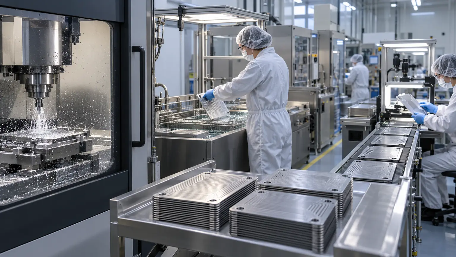
Successful fuel cell bipolar plate machining requires a stable relationship between material, fixture, cutting strategy, tool life, deburring, cleaning, and measurement. Control that relationship early, and a complex flow field becomes a repeatable component rather than a one-off demonstration.

