


A femoral stem is a long, three-dimensional component whose critical relationships can be easy to underestimate in a flat drawing. The taper at the neck, the stem’s longitudinal form, transitions near the shoulder, and any specified surface zones must all be interpreted against the same released definition. A profile can look smooth in a rendering and still be difficult to fixture, finish, or measure consistently.
Femoral stem machining should start with the datum scheme and material condition, then connect each operation to an inspection question. This is a manufacturing discussion for engineers and buyers, not clinical advice about implant selection or surgical technique. The scope is also narrower than a general hip-implant article: a femoral stem and an acetabular cup are different components with different geometry, interfaces, and process concerns.
Keep the part boundary clear
In a hip system, the femoral stem occupies the femoral side of the assembly, while the acetabular component belongs to the socket side. A buyer may procure them together, but combining them into one generic “hip implant manufacturing” article can blur the component-specific decisions. The stem article should focus on its long axis, proximal geometry, connection features, specified surface condition, and how those features are inspected.
Start with the released drawing, model, material specification, and revision. Confirm whether the part is an early design prototype, a dimensional sample, or a component intended for a defined production route. These stages answer different questions. A prototype can help review fit or geometry, but it does not automatically establish a later surface treatment, validated process, or finished-device acceptance.
FDA databases and public device records can provide context for named device families, but a record for one manufacturer or one model should not be generalized to every stem. Use device-specific documentation for regulatory or clinical claims. This article stays with supplier-side manufacturing planning and does not infer approvals from the component name.
Translate the stem geometry into controlled features
A useful drawing review groups features by function. The stem body may include a proximal shoulder, neck, taper, head connection, distal geometry, and one or more finish or coating zones. The exact set depends on the design. For each group, identify which dimensions define size, which controls define form or position, and which datums establish the measurement frame.
Long, curved geometry creates a reference problem: the part may be easy to orient in a fixture but difficult to measure using an assumed straight axis. Make the datum definition explicit. If a centerline is derived from multiple features, define how those features establish it. If a mating taper controls a connection, specify the taper’s angle, contact region, surface condition, and relevant inspection method rather than relying on a nominal drawing silhouette.
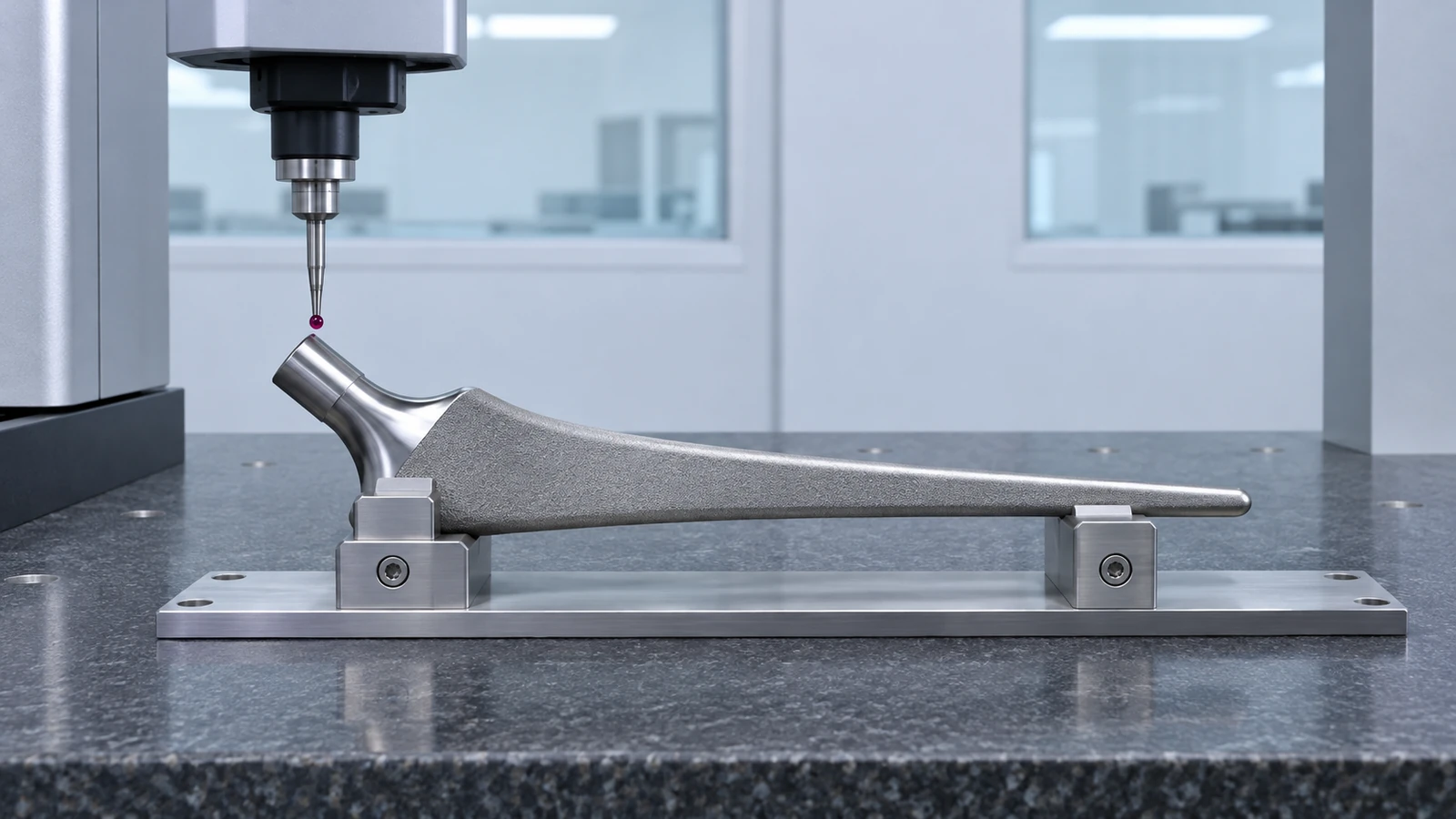
Different surface zones may carry different requirements. A region intended for a specified coating, porous treatment, or other downstream process must be described with its boundary and sequence. A machined zone may require a different finish or dimension from a treated zone. Do not assume that a supplier can infer where one zone ends from a shaded rendering; use controlled drawing callouts and model annotations.
Plan the machining sequence around datums
Begin by identifying the surfaces that establish a stable first setup and the features that depend on them. Depending on stock form and design, the route may combine turning, multi-axis milling, grinding, or other specified operations. The correct sequence is part-specific. It should preserve the relationships in the drawing and account for access, support, stock removal, material condition, and any later treatment.
Roughing and finishing can have different objectives. Roughing creates the general form and removes stock; finishing establishes the final controlled surfaces. If the part is long or has an asymmetric section, fixture support and clamping can affect how it behaves during a cut. A finishing pass performed under a different support condition may produce a released geometry that differs from the in-fixture measurement. State the inspection condition and support method when they matter to acceptance.
Feature transfer between setups deserves a deliberate plan. If a proximal interface and distal feature are machined separately, establish how the second setup references the first. A fixture can constrain movement, but it cannot correct an ambiguous datum scheme. Where a transition or taper is critical, decide whether the datum is recreated from a physical feature, a controlled gauge, or a coordinate reference—and document the method.
Downstream operations change the order. If the drawing specifies heat treatment, coating, porous treatment, blasting, or another surface process, determine which dimensions are measured before and after it, which surfaces need masking, and who controls the process. The machining supplier should quote the specified scope, not assume that a surface condition can be supplied without an agreed responsibility and acceptance plan.
Coordinate surface zones and downstream operations
Surface requirements can coexist on one stem: a connection taper, a machined reference, a treated region, and a transition that must not be damaged. Make a zone map that records the required surface condition, operation sequence, masking boundary, and inspection timing. This is especially important when a process is performed by a different supplier, because the handoff can change both dimensions and traceability.
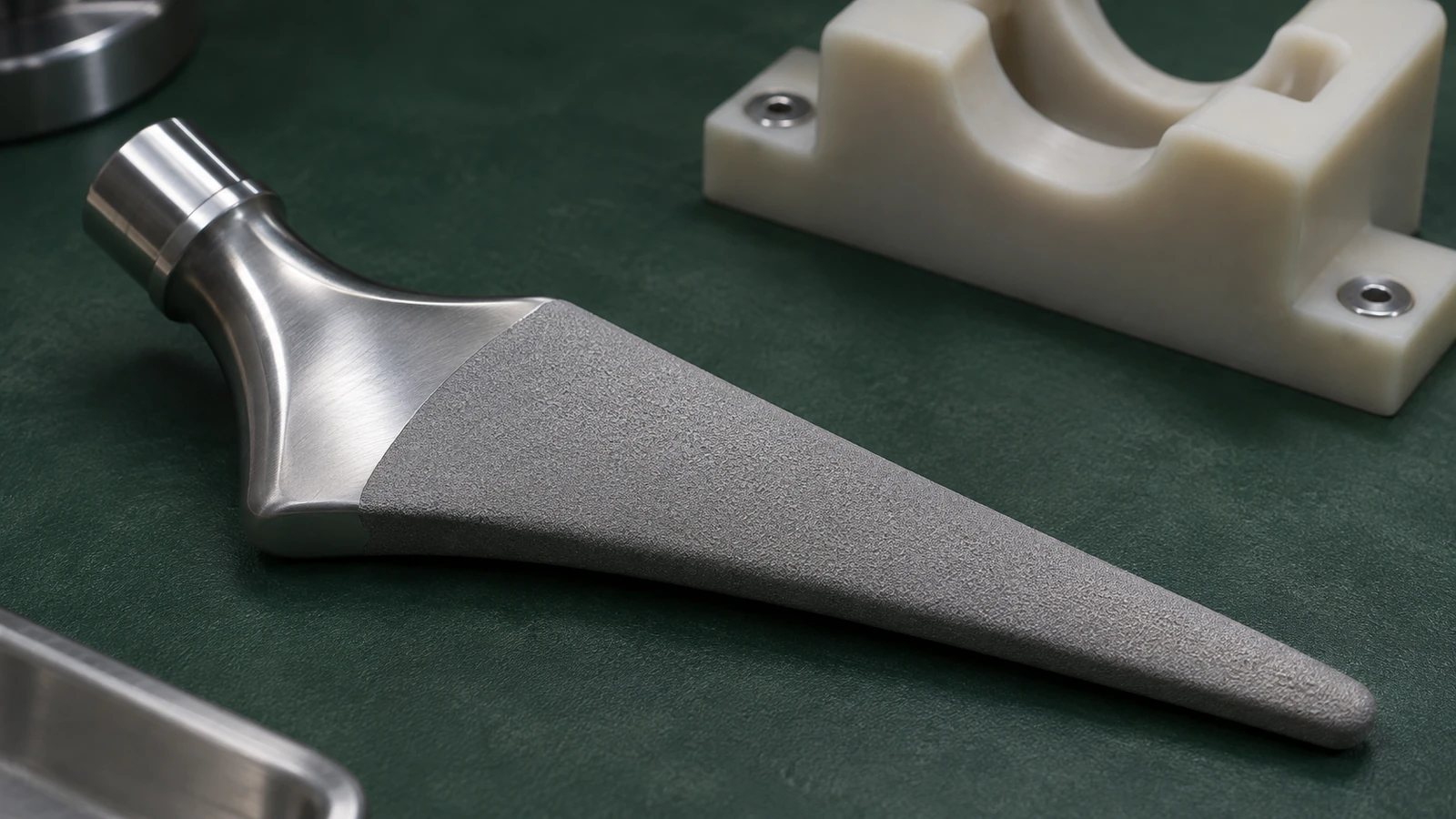
Material selection is equally specific. A drawing may call for a particular titanium alloy, cobalt-chromium alloy, stainless steel, or another material and condition. Those options have different properties and processing behavior; they are not interchangeable by generic family name. State the grade, condition, applicable certification or traceability record, and any customer-approved substitution procedure. If the drawing is incomplete, ask for clarification rather than filling the gap with a typical value.
Surface roughness needs a location and measurement direction. A single general note may not cover a taper, a long stem body, and a treated zone equally. Define how the measurement is taken and whether it applies to the machined condition or the completed condition. Avoid describing an unverified surface as “implant grade” or “biocompatible”; those terms depend on the material, process, device, and evidence beyond a machining operation.
Build an inspection plan around the long axis
Inspection should answer the drawing’s actual questions: Is the stem profile within the specified envelope? Is the connection taper correct? Do the proximal and distal features relate to the defined datum frame? Is the boundary of a surface zone located where the drawing requires? A check of isolated diameters cannot answer all of these.
A coordinate measuring machine, contour measurement, a dedicated gauge, or another method may suit different characteristics. Select equipment based on access, geometry, uncertainty, and the applicable acceptance criteria. The instrument’s name alone is not a method: the report should identify the alignment, datum simulation, measured points or scan path, and any filtering or evaluation rule that affects the result.
For first-article work, align the inspection report to the drawing balloon scheme or a mutually agreed characteristic list. Include the material identity and condition when required, the operation state, and the revision. If a downstream treatment can move or obscure a feature, inspect at the agreed stage and record whether the result is pre- or post-treatment.
For design-development parts, keep the test objective narrow. If the question is whether a taper mates with a supplied component, document the mating reference and fit observations; do not present that as evidence of clinical performance. If the question concerns a surface process, define the relevant coupon, sample, or process evidence through the responsible quality plan rather than infer it from a machined prototype.
Prepare a complete supplier package
A supplier review moves faster when it includes the current 2D drawing, 3D model, revision, exact material and condition, quantity, surface-treatment responsibility, and required inspection records. Mark the features that control a mating interface or a defined surface zone. Include any customer-supplied mating part or gauge if the acceptance plan requires it.
Ask the supplier to state the proposed blank, setup concept, operation sequence, measurement approach, and assumptions about outsourced finishing. If multiple variants exist, identify their common and unique characteristics. That prevents a supplier from applying one route to several drawings whose tapers, length, or surface zones differ.
Jucheng’s related acetabular cup machining article addresses the socket-side component, while its bone screw machining overview covers a separate orthopedic part family. For the stem itself, keep the RFQ grounded in its controlled geometry and required evidence. A drawing-based review of medical device materials can help frame the material discussion, but the device owner remains responsible for the final specification and validation requirements.
FAQ
Is femoral stem machining the same topic as acetabular cup machining?
No. They are separate components on different sides of a hip system and have different geometries and interfaces. Internal links can connect them, but each article should answer its own component-specific manufacturing questions.
Can one machining route be assumed for all femoral stems?
No. Geometry, material, blank, quantity, surface zones, and the drawing’s datum scheme determine the route. A supplier should state the assumptions behind its proposal.
Does machining alone establish implant suitability?
No. Suitability and regulatory acceptance depend on the finished device, intended use, material and process controls, design verification, and applicable evidence. A machining article should not imply clinical or regulatory approval.
What should be agreed before first-article inspection?
Confirm the drawing revision, datum simulation, characteristics to report, measurement method, surface-treatment stage, part identification, and any required traceability documents.

