


A valve spring retainer should be selected and drawn as part of a matched spring, valve, and lock assembly. Outside diameter and low weight are only the beginning. The spring seating steps, lock taper, valve-stem relationship, installed height, and finished contact surfaces decide whether the components sit together as intended. A lighter part that changes those relationships can create a new problem instead of solving an old one.
For engineers developing a prototype, the useful question is which dimensions and material conditions must survive machining, finishing, and assembly. This guide explains how to prepare that information and compare manufacturing options. Engine load limits and operating validation remain the responsibility of the design owner; a dimensional prototype alone does not establish durability.
Draw the spring and lock stack before comparing materials
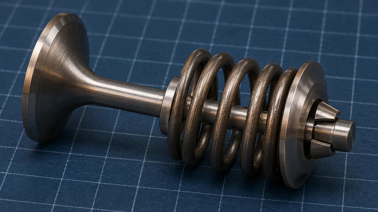
Begin with a section through the assembled valve, split locks, retainer, and spring. Show the actual mating components and their controlled revisions. The retainer must locate the spring while reacting the load through its locking interface. Different spring packages can require different seating diameters, steps, and clearances, even when their nominal outside dimensions appear similar.
Identify whether the drawing refers to a single spring or a nested spring arrangement. Mark which surfaces carry contact and which provide clearance. A corner relief that looks insignificant in an isolated model may determine whether a spring sits flat or touches an unintended edge. Avoid letting a machinist infer the intended seating surface from a rendered image.
The locks need the same attention. A stated taper angle is not enough without the relevant diameter, axial location, contact extent, and matching lock specification. Do not assume parts are interchangeable because both are sold with the same angle description. TOMEI’s retainer instructions explicitly pair its products with specified spring applications, illustrating why an assembly identity belongs in the drawing package.
Titanium or steel: compare the complete requirement
For a valve spring retainer, titanium is often considered when reducing moving mass matters. Steel can be attractive when cost, section geometry, wear behavior, and an established material specification favor it. Neither material family is an automatic answer. Compare exact grades and conditions, then assess how the design will carry load and maintain its contacts over the intended operating conditions.
The drawing should state whether a material property refers to incoming stock or the finished component. Heat treatment, machining allowance, surface processing, and inspection timing can affect the delivered geometry. A stock certificate establishes material information; it does not show that the lock contact or spring seating face meets its dimensional requirement.
For a titanium route, use the titanium CNC machining material page to frame the manufacturing discussion. Confirm the approved grade before comparing cutting effort or finishing choices. Avoid substituting an available alloy solely because its published tensile strength is similar to another alloy’s value.
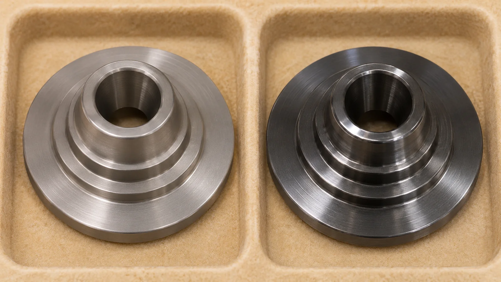
For a steel route, discuss the required condition and sequence with the drawing owner. Machining an easy-to-cut blank and processing it later may create different inspection needs from finishing already treated stock. The correct comparison includes processing risk and verification effort, rather than only the price of the bar or the cycle time of one operation.
Installed height can change without an obvious diameter error
The axial stack includes the lock position on the valve, the retainer’s mating geometry, and the spring seating surface. A dimension taken from the top face of the retainer may be convenient to inspect yet fail to describe the installed spring position. Choose references that express the actual assembly relationship and identify how the inspection reproduces it.
Consider an illustrative development scenario: two retainers have matching outside diameters and spring steps, but the assembled seating height differs. Before changing the spring, compare the locks, the taper contact position, and the axial distance from that contact to the seating surface. A small mismatch at the lock interface can move the retainer without producing an obvious external size difference.
This is a hypothetical engineering example, not a Jucheng customer case. The point is to isolate the stack rather than respond by tightening every tolerance. Ask which interface controls the displacement, how the assembly was seated for measurement, and whether finishing or burrs changed the contact. Record the mating hardware used in the check.
Turning establishes the shape; edge control preserves the fit
Many retainer features are rotational, making CNC turning a reasonable route to review for prototypes. The actual plan depends on the geometry, approved material, stock condition, and access. If a secondary operation is needed, preserve the reference that relates the locking feature to the spring seat. A second setup should have a defined locating strategy.
Thin sections and recessed steps need practical tool access. Review the smallest internal radius, the space for the tool nose, and the stability of the remaining section. A perfectly sharp model corner may be impossible to reproduce with the proposed cutter. Resolve the allowed radius or relief before quoting instead of making an undocumented change during production.
Deburring should protect the functional boundaries. Excessive edge breaking can alter a narrow seating land or remove material near a lock contact. Specify the critical edges and distinguish an acceptable relief from an uncontrolled chamfer. Where a treatment changes dimensions, agree whether the contact is measured before or after that treatment and how it is protected during handling.
Build an inspection plan around three questions
First, does the retainer match its drawing? Check the relevant diameters, axial distances, profile, and surface requirements from the specified references. An external caliper reading cannot describe an internal taper or establish how that taper relates to the spring seat. Select the measuring method for the feature and its tolerance.
Second, does the matched assembly seat as intended? An approved lock set or defined inspection fixture can help examine the stack. State the seating condition and avoid forcing a mismatch into apparent acceptance. A functional assembly check provides useful evidence, but it does not replace a dimensional report when the purchase specification requires both.
Third, what remains for operating validation? Static geometry does not demonstrate high-speed stability, fatigue life, or compatibility with an entire engine system. Keep those acceptance responsibilities visible. The manufacturing record should say which characteristics were measured, which mating references were used, and which performance questions remain outside the prototype order.
Give the prototype supplier a usable review package
Send the component model, section drawing, matched spring and lock information, material specification, quantity, finishing requirements, and identified critical features. Explain whether the sample will check packaging, assembly, mass, or another defined development objective. That purpose helps decide where inspection effort belongs and which unfinished questions must be resolved before cutting metal.
For a valve spring retainer prototype review, Jucheng’s automotive prototyping scope provides a starting point for discussing machined component geometry. Ask for a route assessment against the actual files. Material, tolerances, special processing, and any testing should be agreed for the project rather than inferred from the component name.
Frequently asked questions
Is a titanium valve spring retainer always the better choice?
No. Lower mass is one design consideration. The approved alloy, contact geometry, wear behavior, processing condition, budget, and required validation all influence the decision. Compare a complete specification instead of selecting from a material label.
Can matching outside diameters prove compatibility?
No. The lock interface, spring seating steps, axial stack, and surrounding clearances also matter. Compatibility requires the controlled mating parts and defined assembly checks, not a single external measurement.
Should every surface receive the tightest available tolerance?
No. Identify the surfaces that control seating and contact, then apply justified limits. Unnecessary tolerances add machining and inspection effort while leaving an incorrectly defined interface unresolved.
Reference and scope
TOMEI’s titanium retainer instructions provide a manufacturer-specific example of matched spring applications. Their dimensions, application restrictions, and performance statements must not be generalized to a custom component or represented as Jucheng validation.

