


A camshaft thrust plate helps control axial movement through its relationship with the shaft, locating shoulders, and mounting structure. Its thickness matters, but thickness alone does not establish the assembled end play. Contact-face geometry, seating conditions, neighboring components, and the design’s measurement convention belong in the same review.
For an engineering team ordering a custom prototype, the aim is to define that relationship before choosing a material or machining route. This guide addresses the plate and its manufacturing handoff. It does not provide an engine repair procedure or a universal running clearance; the approved engine design must supply those requirements.
Start with the axial stack, not the plate outline
Sketch a section through the restrained camshaft and identify the two limits of axial travel. Mark the surfaces that actually make contact at each limit. Depending on the construction, the stack may involve a shaft shoulder, gear or hub, plate, spacer, and housing. Do not assume that every engine uses the same arrangement or that every visible face carries thrust.
Distinguish the plate’s mounting face from its working contact face. A drawing can specify the correct overall thickness while leaving the functional separation between these faces ambiguous. Local recesses, raised lands, coatings, or a fitted neighboring component may affect the relevant dimension. State the references that express the installed relationship rather than dimensioning only from a convenient external edge.
Write down the condition in which end play is assessed. The approved procedure may depend on a particular assembly state, locating hardware, and method of applying axial movement. Prototype inspection should follow the agreed convention. A loose-part measurement and an assembled displacement measurement answer different questions, so they should appear as separate checks where both are needed.
Separate thickness, flatness, and face relationship
Thickness describes the distance between specified surfaces. Flatness describes the shape of a surface. Parallelism or another specified geometric relationship describes orientation relative to a reference. These controls can address different failure modes. A plate can pass a thickness check at selected points while a local high region prevents full seating against the housing.
For a camshaft thrust plate drawing, identify where thickness is measured and which portions of the faces count as functional lands. A micrometer placed across a relief does not represent the contact stack. Likewise, an average reading across several locations can hide a local condition that matters at assembly. Choose the report locations and method to suit the geometry.
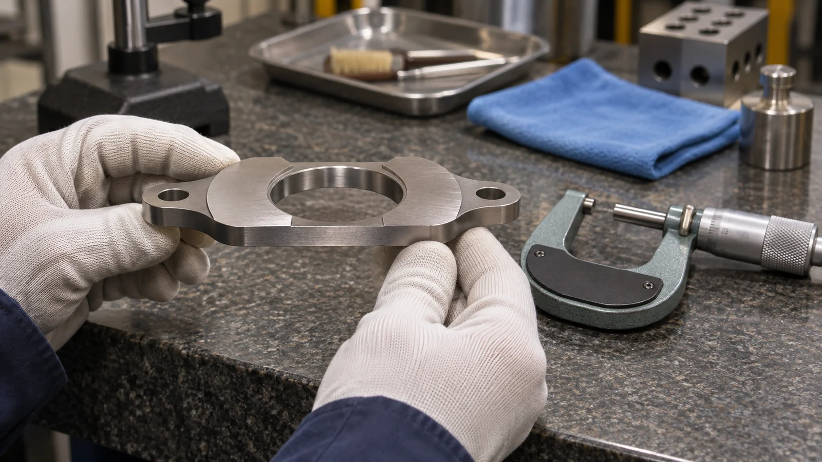
Clamping introduces another distinction. If the mounting arrangement changes the plate’s shape, the inspection condition should explain whether the relevant requirement applies free-state or installed. The machine shop should not flatten a flexible sample in a fixture and quietly report that result as an unconstrained surface. Document support locations when they affect the measurement decision.
Material and surface condition belong to the same decision
The plate’s approved material depends on its contact environment and the engine design. Steel grades, processing conditions, and surface requirements cannot be exchanged solely because the parts have the same outline. The supplier needs an exact material specification and delivery condition, together with any required treatment and records. A broad description such as hardened steel leaves the route unresolved.
Use the alloy steel machining page to frame questions about a proposed steel component, then confirm the actual grade. Stock condition affects tool selection, workholding, and the sequence of operations. If a specialized finishing operation is necessary, identify it explicitly; a CNC quotation does not automatically include grinding, treatment validation, or engine testing.
Where a treatment affects dimensions, identify which operation establishes the final functional faces. An inspection performed before that operation may be useful for process control but does not verify the delivered plate. Keep appearance requirements separate from contact requirements. A polished-looking part is not evidence that the required profile, surface condition, or wear performance has been achieved.
Plan machining around broad faces and local features
The blank route depends on geometry, quantity, material, and the purpose of the sample. A cut blank followed by machining may suit one development stage; machining from stock may suit another. Compare how each route preserves stock for the working faces and provides a stable reference for mounting holes, slots, recesses, and edge features.
Removing material from a broad, relatively thin section can change its shape. Review support, cutting access, and the sequence in which the faces and openings are finished. A fixture that works for a solid blank may support the remaining plate poorly after its central opening is cut. The route should explain how the functional surfaces remain accessible and protected.
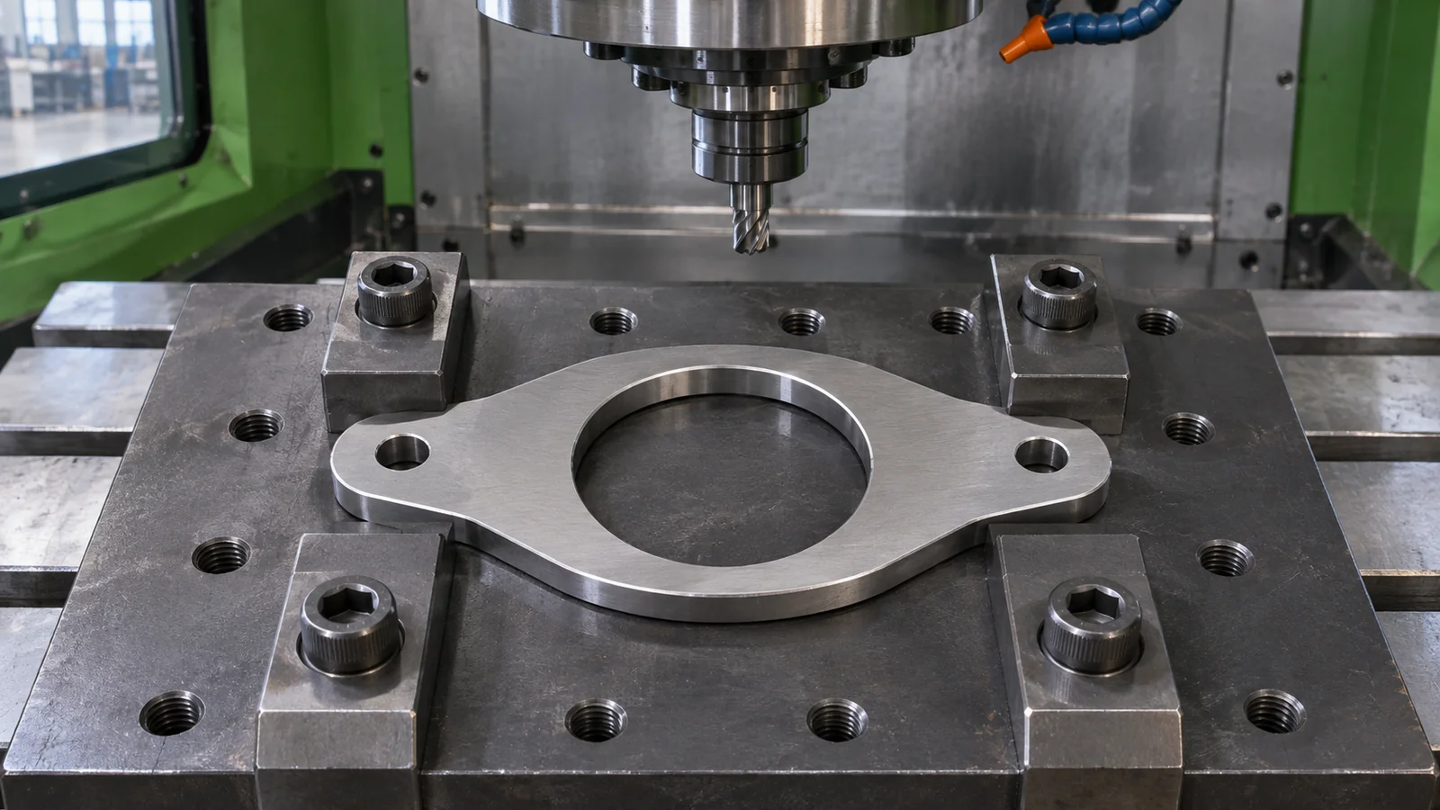
Edge finishing needs its own instructions near narrow contact lands. Removing a burr is necessary where specified, but an uncontrolled chamfer can reduce the intended contact region. Identify the edges that need protection and the permitted break or relief. If an access problem requires a design change, return it to the drawing owner before changing the component.
A thickness correction can miss the real cause
Consider a hypothetical prototype assembly with less axial travel than expected, even though the plate meets its stated thickness limits. First confirm the drawing revisions and the mating stack. Then inspect seating faces, recess depths, locating features, and any burr or contamination that could hold a surface away from its intended position. Preserve the condition before reworking the sample.
If the plate sits correctly but the stack still differs, compare the neighboring shoulder or spacer dimensions and the assembly measurement method. Automatically making the plate thinner could conceal a different dimensional error and change the design’s contact relationship. A controlled comparison should identify which term in the stack changed and which requirement the proposed correction protects.
This scenario is illustrative, not a Jucheng customer case. It shows why a useful report connects individual dimensions to the assembled result. The design owner can then decide whether the issue belongs to the plate, another component, the inspection setup, or an incomplete requirement. That decision is more valuable than repeatedly cutting samples to chase an unexplained reading.
Define a prototype acceptance package
A camshaft thrust plate development review should include the component model, sectioned stack, material condition, critical faces, mating references, sample quantity, and intended use. Jucheng can review the proposed machined component scope against those files and discuss access, sequence, and inspection requirements before a route is agreed.
Separate three results in the handoff: conformity of the individual plate, behavior of the defined assembly, and any operating validation still required. An acceptable dimensional prototype does not establish engine durability. If the sample will support an engine program, the responsible team must define the test conditions, acceptance evidence, and permitted use independently of the manufacturing report.
Frequently asked questions
Does a thicker camshaft thrust plate always reduce end play?
Only the actual stack determines how a dimensional change affects travel. Identify the working faces and neighboring components before predicting the result. Do not apply a general thickness rule to an unfamiliar construction.
Can plate thickness replace a flatness requirement?
No. Thickness and surface shape describe different characteristics. A local high area or an incorrectly seated face may matter even when selected thickness measurements meet their limits.
Should the prototype be inspected after finishing?
The acceptance record should represent the specified delivered condition. Intermediate checks can support process control, but any later operation that changes a functional feature needs an appropriate verification plan.
Source context
Navistar’s published gear-train investigation notice, hosted by NHTSA, identifies the thrust plate within a particular engine assembly investigation. It is model-specific technical context, not a source of universal dimensions or a claim that a custom prototype is approved for service.

