


Small does not automatically mean difficult to mold. A tiny connector with generous radii may be straightforward, while a larger diagnostic cartridge can contain channels that are difficult to fill, release and measure. In micro molding medical devices, the decisive issue is whether the manufacturing route can reproduce the functional features consistently and produce credible evidence that those features meet their requirements.
Before approving a mold, identify the feature that controls device performance, its acceptable variation and the method that will inspect it. Then work backward through demolding, cavity construction, venting, gating and material preparation. This is a different decision from choosing a molding press by the overall dimensions of the part.
Start With the Feature That Can Stop the Device
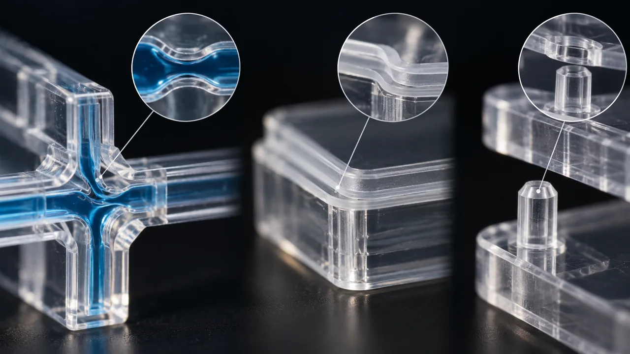
A microfluidic junction, a sealing lip and a miniature locating pin fail in different ways. A junction may restrict flow; a lip may leak when flash interrupts its contact; a pin may position an optical component incorrectly. These functions require different drawings and different evidence, even if all three components use the same polymer.
Separate critical-to-function features from convenient reference dimensions. Record what each feature does, which mating component it interacts with and how it could fail. Avoid specifying an equally tight tolerance on every dimension: doing so can increase tooling and inspection effort without reducing the actual device risk.
For a diagnostic channel, depth and width may be insufficient descriptions. Entrance shape, a local restriction, the surface condition and the geometry after bonding can also matter. For a sealing lip, define the functional land and allowable flash location rather than relying on a vague instruction such as no visible defects.
The broader medical device manufacturing processes overview helps compare available routes. Here, the question is narrower: which features require a specialized molding and measurement strategy, and what should be settled before the tool is cut?
A Feasibility Review Needs More Than Part Size
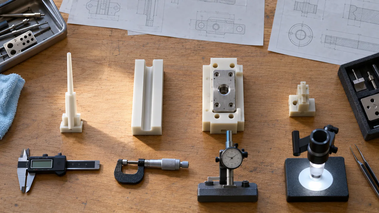
Use a feature-by-feature review instead of a single minimum-size claim. The following table is a planning framework, not a statement of Jucheng’s guaranteed tolerances or equipment limits.
| Feature or condition | Manufacturing concern | Evidence to request |
|---|---|---|
| Long, narrow channel | Flow hesitation, trapped air and local short shots | Filling study and measurements at the end of flow |
| Thin sealing edge | Flash, distortion and handling damage | Edge inspection linked to a seal test |
| Slender core feature | Tool deflection, wear and difficult release | Core construction review and cavity-specific data |
| Small metal insert | Position drift, heating and retention | Insert location checks and representative pull testing |
| Fine optical or locating detail | Surface replication and alignment | Relevant surface or dimensional measurements |
| Extremely small shot relative to machine capacity | Limited useful process adjustment range | A justified machine, runner and shot strategy |
A supplier should explain the proposed trade-offs, not simply answer that the part is possible. Ask whether a slightly larger radius, different gate location or removable insert would improve robustness without changing the intended function. These changes are cheapest before drawings and device interfaces are frozen.
Gate, Vent and Release Form One System
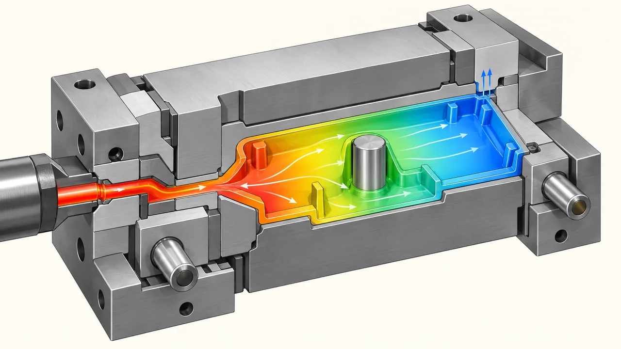
Gate position determines how the flow reaches a critical feature and where a vestige remains. On a tiny component, that vestige can occupy a meaningful fraction of the available surface. Its location must therefore be assessed against assembly, sealing and handling requirements, not only against filling behavior.
Venting is equally consequential. Air must leave the last region to fill without creating a vent that permits unacceptable flash. A vent that is adequate during initial trials may behave differently after residue accumulates or the tool wears. Include accessible cleaning and maintenance provisions in the tool review.
Demolding can destroy an otherwise well-replicated feature. Thin walls may grip a core, flexible details may stretch, and ejection forces may deform the measurement datums. Review the load path from ejectors to the part, the surfaces that can tolerate witness marks and whether the part will remain attached to a carrier during handling.
For complex components, discuss Schnellwerkzeug as a way to investigate selected risks before committing to a production tool. A trial tool does not automatically reproduce production cooling, cavity balance or tool life. Define which question the trial answers and which questions remain open.
Do Not Repair a Drawing Problem With Process Settings
An aggressive filling adjustment may overcome one short shot while worsening flash elsewhere. A longer hold may change the fit of a locating feature. If acceptable settings exist only in a very narrow window, reassess the geometry and tooling rather than treating a single good shot as proof of readiness.
Record interactions between variables during trials. Keep the resin grade, conditioning, mold condition and handling method traceable so that a change in one element does not masquerade as a successful process improvement.
Material Choice Changes the Microgeometry
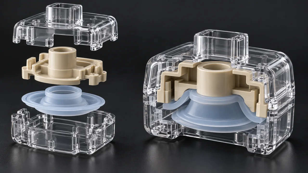
Select a specific grade rather than a generic family name. Flow behavior, shrinkage, additives, moisture sensitivity and the intended sterilization exposure influence whether fine details can be replicated and retained. A material that suits a large housing is not automatically suitable for a delicate microfeature.
PC can be considered where transparency and toughness are important, while PP may be considered for lightweight components or compliant features. PEEK may enter discussions involving demanding temperature or chemical conditions, but it brings a different processing challenge. None of these broad examples establishes suitability for a particular patient-contact application.
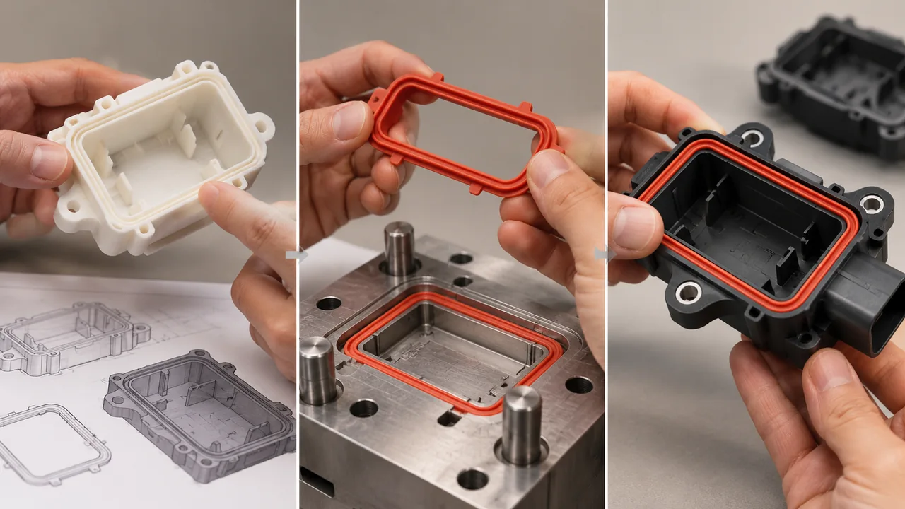
LSR presents another set of trade-offs: flexibility can help a seal perform its function but can complicate gripping, flash inspection and measurement without deformation. Compare the finished geometry and the required hardness with the tooling and handling plan, rather than treating a soft material as an automatic solution to a difficult fit.
Material conditioning instructions should come from the selected supplier’s grade documentation. Do not copy a drying recipe from another resin. The purchase specification should also address permitted additives, substitutions and material identification so a later procurement change does not invalidate the original development evidence.
Measure Without Moving the Answer
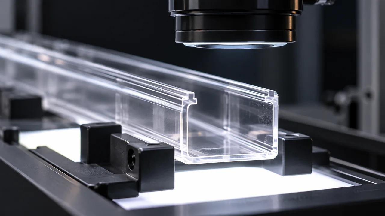
A feature is not controlled merely because a microscope can display it. The measurement must have suitable resolution, a reproducible reference and a way to distinguish true variation from fixture, lighting or operator effects. Transparent parts, rounded edges and flexible seals may need different strategies.
For optical inspection, define the edge-detection convention and the relevant viewing direction. Reflections can shift an apparent edge; an image taken at an angle can change the apparent width. For contact methods, assess whether probe force or clamping changes the shape being measured.
Inspect features from different cavities separately during development. Pooling all measurements can hide a cavity that consistently approaches a limit. Similarly, measure after the defined conditioning period and, where appropriate, after the downstream bonding or sterilization exposure that could change the geometry.
Keep dimensional inspection distinct from functional testing. A channel may be dimensionally acceptable but contain an obstruction; a seal may meet its dimensions yet fail because of local damage. A useful acceptance plan pairs measurements with the physical function they are intended to protect.
From Trial Shots to a Purchase-Ready Specification
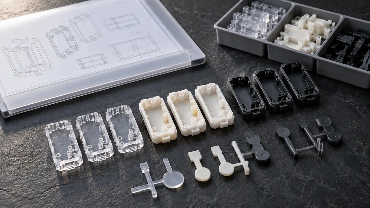
Prepare a release package that includes the controlled drawing, exact resin, critical features, approved inspection method and handling requirements. It should explain acceptable gate and ejector marks, flash limits at functional surfaces and what happens when the tool is maintained or modified.
The quotation for low-volume injection molding should separate tooling work, trial quantities, inspection effort and production assumptions. Comparing only the piece price can conceal the cost of a difficult measurement system or frequent tool maintenance.
Jucheng can be approached with CAD data and the intended component function for a manufacturing review. Treat the resulting proposal as an engineering discussion: confirm project-specific capability, documentation and testing responsibilities before making regulatory or production commitments. Clinical suitability and device approval remain separate from successful part manufacture.
Questions to Resolve Before Ordering the Mold
Is every miniature medical part a micro-molding project?
No. Overall size is only one indicator. Fine functional details, shot control, release behavior, handling and inspection can create a specialized problem even on a larger component. Conversely, some small parts can be made with a conventional, well-matched molding route.
Can a printed prototype prove that a molded channel will work?
A printed prototype can investigate layout or assembly, but it may differ in roughness, material behavior and feature fidelity. Use it for an identified learning objective; obtain representative molded samples when the question depends on the final process.
Should tighter tolerances solve a leaking micro seal?
Not necessarily. Flash location, surface damage, compression, mating geometry and material behavior may dominate the leak. Establish the failure mechanism before narrowing a dimension that may not be responsible.
What belongs in the first supplier discussion?
Provide the functional features, intended material, expected quantities, mating parts and proposed acceptance tests. Include handling and sterilization assumptions. That information allows a supplier to evaluate the complete manufacturing problem rather than quoting a shape alone.

