


Medical device thermal management includes the physical route by which heat moves from components through interfaces and into the surrounding environment. A housing is not merely a box around the electronics: it can carry heat, obstruct airflow, constrain an interface or create a surface the user touches. These roles must be considered together.
This guide focuses on the manufactured enclosure, heat spreader, mounting structure and assembled interfaces of equipment such as diagnostic instruments. It is not a discussion of therapeutic heating or a substitute for electrical-safety assessment. Establish the device’s relevant temperature requirements with qualified designers before selecting a housing material or cooling arrangement.
Draw the Heat Path Before Changing the Material

Identify the heat sources, operating conditions and proposed dissipation route. Follow the path through each physical contact: component to spreader, spreader to chassis, chassis to external surface and surface to the environment. A highly conductive housing is of limited value if the upstream contact is poor.
Separate local hot spots from average enclosure temperature. A sensor or nearby polymer feature may experience a different condition from the surface used for a convenient temperature measurement. Place measurements around the physical questions rather than only where access is easiest.
For a simplified steady-state illustration, temperature rise can be expressed as heat flow multiplied by an equivalent thermal resistance. If an assumed 8 W passes through a modeled 3 K/W path, the modeled rise is 24 K. This is a teaching example, not a device safety limit or a complete thermal model. Real equipment can require transient analysis and multiple interacting paths.
Use the medical device design guidelines parent page for broader design constraints. Thermal decisions should be connected to those requirements, not optimized independently of handling, cleaning and structural function.
Compare Contact Quality With Bulk Conductivity

Aluminum or copper may be considered for a conductive path, but the relevant result depends on geometry and interfaces. A thick block that does not contact the source correctly can perform poorly. A thinner component with a controlled interface may answer the actual design question better.
Review flatness, roughness, contact area and the intended assembly load. Thermal interface material can accommodate selected gaps, but it should not be treated as a universal repair for uncontrolled geometry. Its thickness and compression state need to be appropriate for the design.
| Interface condition | Potential consequence | Manufacturing question |
|---|---|---|
| Mating surfaces not adequately flat | Reduced effective contact | How are the relevant surfaces made and inspected? |
| Uncontrolled gap | Variable interface thickness | Which locating features establish the gap? |
| Uneven fastening | Local contact and distortion | What assembly sequence and conditions apply? |
| Coating on a contact surface | Changed interface behavior | Should the surface be treated or masked? |
| Flexible supporting wall | Contact changes under load | Does the structural design maintain the interface? |
CNC-Bearbeitung may be suitable for investigating controlled mating features or a prototype heat spreader. Specify the surfaces that matter and their finished condition rather than requesting uniformly tight tolerances throughout the part.
Do Not Let the Drawing Hide the Assembly State
A spreader measured on its own may change shape when installed. Evaluate the assembled condition where it determines contact. Likewise, a thermal pad selected from a datasheet must be considered under its actual compression and exposure, not only in an ideal specimen.
Enclosure Openings Trade Heat Flow Against Other Requirements

Ventilation can help move heat but can also affect ingress protection, cleaning access, acoustic behavior and user contact. A fan is not a complete thermal solution if its flow path is blocked by internal structures or the external installation.
For a sealed or largely closed enclosure, the external surfaces and internal heat path may become especially important. Consider how heat reaches those surfaces and whether a user can contact them. A route that protects electronics can still create an unacceptable touch condition.
Eaton’s medical-device thermal discussion highlights the interaction between device shape, dissipation and user exposure. The manufacturing implication is to coordinate enclosure and cooling geometry early rather than attempt to add a heat sink after the physical form is fixed.
Do not assign a universal surface-temperature limit from a general article. Applicable requirements depend on the device, contact and use conditions. The responsible team should establish and evaluate the relevant limits, while manufacturing supports the specified physical configuration.
Für sheet metal enclosures, review formed geometry, seams and fastening as well as opening area. A local distortion or assembly gap can alter both structural and thermal behavior. Confirm whether the proposed production route reproduces the prototype’s interfaces.
Run a Prototype Test That Represents the Heat Source

A cosmetic housing around inactive electronics cannot establish thermal performance. Use a representative heat source or a justified simulator and document its location, distribution and operation. If the simulator differs from the intended component, assess whether that difference affects the conclusion.
Control ambient conditions, mounting orientation and the surrounding installation. A device on an open bench may dissipate differently from one installed inside a cabinet, on a stand or near another surface. Record the relevant configuration rather than attributing every difference to the enclosure material.
Measure temperatures at the locations that protect function and user requirements. Monitor the operating sequence long enough to address the planned question, including transient behavior where relevant. The appropriate method and duration need a technical basis rather than a convenient fixed interval.
The existing medical device enclosure prototype article supports the wider sample plan. Identify which prototype route represents the heat path: a printed polymer housing may support layout while a metal sample is needed to investigate the proposed conductive structure.
Inspect the physical interfaces after the test. A shifted pad, loosened fastener or distorted cover can explain a change that the temperature record alone does not reveal. Preserve the hardware state before disassembly removes that evidence.
Release the Heat Path With the Mechanical Package
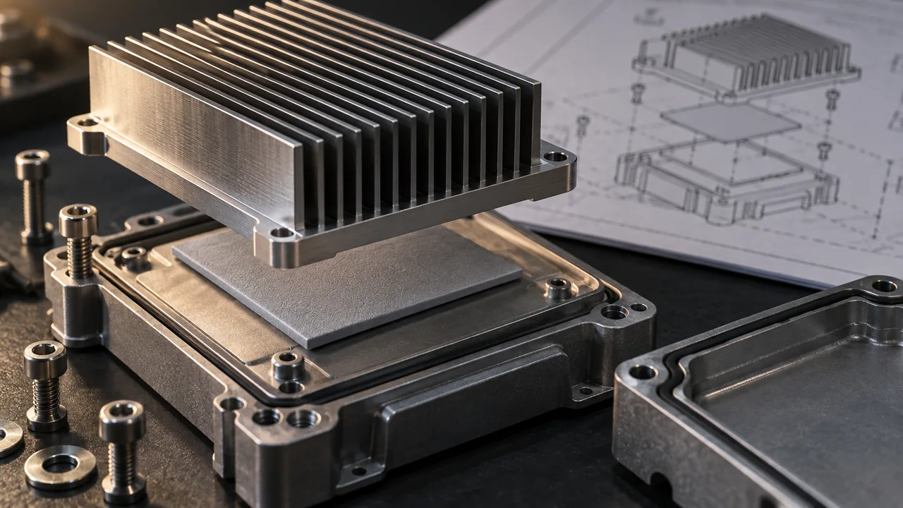
Document the material, critical contact surfaces, interface materials and assembly conditions. Identify finishing masks and the measurements needed to establish the relevant geometry. If production changes the material or fabrication route, assess whether the thermal evidence remains representative.
Review tolerance accumulation around the contact, not only the heat-spreader drawing. Housing, bracket, fastener and electronic component dimensions can combine to create an unintended gap. A complete assembly review helps identify the feature that actually controls the thermal interface.
The component manufacturer should confirm the fabrication and inspection scope, while the device team owns the overall thermal requirements and safety assessment. Jucheng can be asked to review the enclosure and metal-component route against a defined thermal-interface drawing; project-specific capability and specialist testing responsibilities still require confirmation.
Will a Larger Heat Sink Always Solve the Problem?
No. Poor source contact, an obstructed dissipation path or unsuitable installation can limit performance. Diagnose the controlling resistance and relevant boundary conditions before adding mass or changing the enclosure.
Can We Replace the Prototype Metal With Plastic in Production?
Only after assessing the effect on the heat path and other requirements. A change that preserves external shape can still alter conductivity, contact behavior and deformation. Treat material and route changes as technical decisions requiring appropriate evidence.

