


A dental scan body links a physical implant interface to a digital representation of position and orientation. Its base must seat in the defined way, while its visible geometry must correspond to the correct digital reference. Checking only the outside dimensions or only the implant connection leaves part of that chain unverified.
For a component development team, the useful manufacturing task is to keep the scan region, connection, material, surface state, and library revision consistent. This article addresses prototype definition and inspection. It does not provide clinical scanning instructions, implant-selection advice, or a claim that a custom component is validated for patient use.
Define the physical-to-digital chain before cutting a sample
Begin with the controlled assembly model, the intended implant or abutment-level connection, and the digital reference used to interpret the scan region. Identify what information the visible shape carries: height, angular orientation, rotational indexing, or another design-specific relationship. The base and the optical region should not be released as unrelated drawings.
The recognition geometry needs an explicit relationship to the seated connection. A plane, asymmetrical feature, or other recognizable shape can look correct while being rotated or displaced relative to the base. The resulting part may fit physically yet represent the wrong orientation digitally. Define the relevant axis, seating reference, and angular relationship in the controlled model and drawing.
Library identity belongs in configuration control. Straumann’s scanbody information connects its components with corresponding CAD libraries. That is an example of a coordinated system, not a compatibility claim for a custom part. Record the authorized library name and revision without assuming that a similar silhouette will be recognized correctly.
Decide whether the scan region and base are one component
Monolithic and assembled designs create different manufacturing questions. A one-piece component keeps the base and recognition features within one part, but the material and surface must serve both roles. A separate scan region and base can allow different material choices, yet introduces an additional locating and retention interface that must preserve their relationship.
For an assembled dental scan body, define what prevents relative rotation, what establishes axial seating, and how those features are inspected. An adhesive joint, interference interface, or mechanical connection should not be inferred from a rendered model. The design owner needs to specify the construction, allowable assembly variation, and required verification.
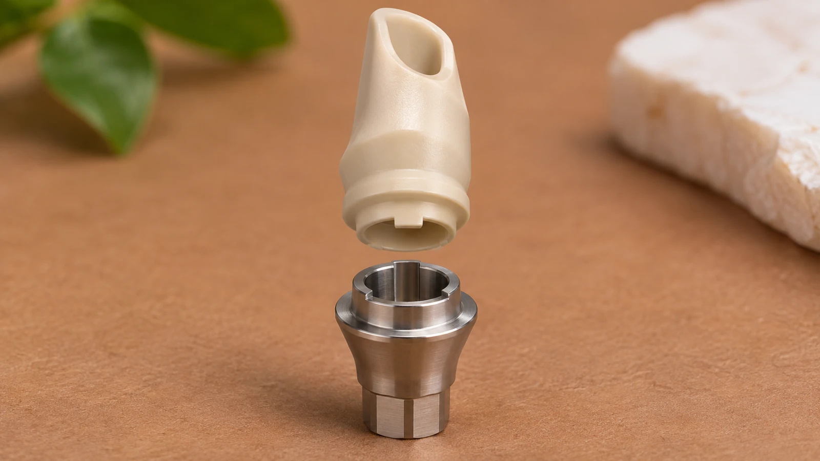
Also decide which state the drawing controls. Dimensions of the separate scan region may be useful for component production, while the key recognition-to-base relationship may apply only after assembly. Record both where needed. A report that verifies each loose part but never checks their assembled orientation can miss the exact relationship the system depends on.
Compare material and surface as a scanning combination
PEEK and titanium are relevant material candidates, but neither should be presented as universally more accurate. The scanner, geometry, surface condition, visibility, reference method, and experimental conditions all influence reported results. Choose the approved grade and construction for the development objective rather than copying a ranking from a single study.
An original 2025 study of scan body material, length, and top design evaluated several modified prototypes under a particular setup. Its findings show why geometry and surface reflectance deserve coordinated review. They do not establish a general tolerance for every scan body, a universal material winner, or performance of a Jucheng component.
Die PEEK machining page und titanium machining page provide material-service context for a manufacturing discussion. Confirm the actual grade, condition, and process scope. A material certificate does not validate optical recognition, clinical suitability, or a sterilization cycle.
Surface processing must preserve the released geometry. A treatment intended to alter reflectance can also affect edges or dimensions, depending on the process. Identify protected features and the final inspection state. Do not approve a surface by appearance alone; describe the characteristic to be controlled and the evidence needed for both geometric and optical assessment.
Recognition features need access and a measurable definition
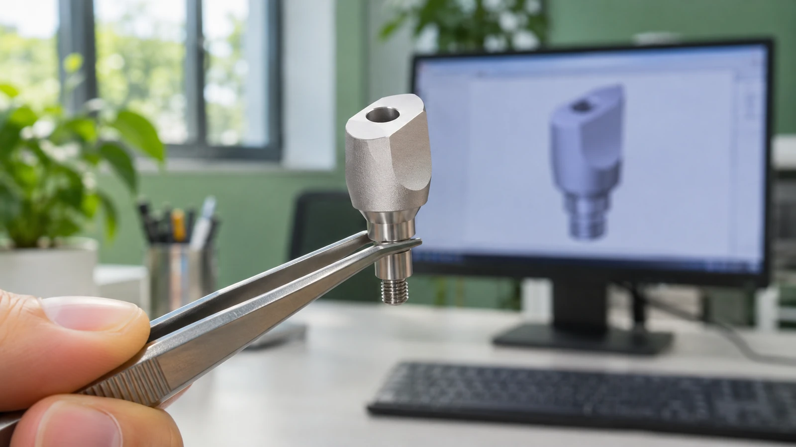
Small flats, top surfaces, screw-access openings, and transitions can determine which regions remain visible and distinguishable. The development review should identify which features are essential to recognition and which provide assembly or driver access. A manufacturing change that simplifies a corner may alter the intended digital shape, even if it improves cutter access.
State the allowed radii, edge treatment, and location of the recognition features relative to the connection. For tiny geometries, inspectability is a design question as well as a machine capability question. An accessible reference or a justified optical method may be needed to measure a relationship that cannot be reached conveniently by a contact probe.
Keep the screw-access requirement visible during this review. Enlarging an opening can change the remaining top surface, while reducing it can affect tool access. Those consequences should be assessed together rather than allowing machining, assembly, and digital-reference teams to optimize separate features independently. Any approved change needs to remain consistent across model, drawing, and library reference.
Separate seating, geometry, and digital verification
Use three distinct evidence paths. First, inspect the connection and the specified seating relationship. Second, measure the recognition geometry relative to that connection in the required assembly state. Third, perform the defined digital evaluation using the correct reference data and agreed scanning conditions. A successful result in one path does not automatically establish the other two.
Reference artifacts and reporting conventions matter. The method used to align a measured shape to a reference can influence the reported deviation. The development team should define the comparison method and the characteristics that determine acceptance, rather than relying on an unexplained overall best-fit number. Preserve the raw configuration and revision information needed to interpret the report.
For repeat-use concepts, any assessment after reprocessing must follow an approved device-specific plan. It may need to examine more than cosmetic change, including the relevant connection and recognition relationships. A general statement that PEEK or titanium can withstand a temperature does not validate a finished assembly or authorize a reuse policy.
Resolve a rotational mismatch without guessing its cause
Consider a hypothetical prototype that seats in its reference connection, but whose digital comparison shows an unexpected rotation. Confirm the library revision, orientation convention, and scan-region-to-base relationship first. Check whether a separate recognition component shifted during assembly and whether the physical reference matches the one used in the digital file.
Only then assess whether surface visibility or the comparison method explains the result. Recutting the external flat before confirming the reference can create another part that compensates for a configuration error. This is an illustrative engineering scenario, not a customer case. Its purpose is to keep physical manufacture and digital interpretation traceable to the same definition.
For a dental scan body prototype review, Jucheng needs the controlled component and assembly files, authorized interface information, material and surface specifications, library reference identity, and sample acceptance scope. This allows machining questions to be resolved alongside the intended verification, while the device manufacturer retains responsibility for system and clinical validation.
Frequently asked questions
Does a good implant fit prove correct scan transfer?
No. Seating establishes part of the chain. The recognition geometry must also relate correctly to the base and the approved digital reference, followed by the required digital evaluation.
Can PEEK be replaced with titanium without updating the review?
No. Material and surface changes can affect manufacturing, assembly behavior, and scanning. Assess the complete revised design and its verification needs rather than treating the substitution as a purchasing change.
Should the drawing reference the CAD library revision?
Configuration records should identify the authorized reference used to interpret the component. The exact document arrangement can vary, but the connection between physical revision and digital definition must remain unambiguous.

