


Two sheets can carry the same alloy designation and behave differently under the same forming tool. One takes the contour; the other springs open, marks at the bend or develops a crack. Before changing the die, check what material condition entered the operation.
Aircraft sheet metal forming converts flat stock into controlled three-dimensional shapes through plastic deformation. A reliable route connects the alloy and temper, sheet direction, tooling, deformation sequence and final inspection condition. Producing the right silhouette is not enough if the required material properties or surface integrity have been lost.
The same alloy can need a different forming route
An alloy name identifies a family of chemistry, not the complete forming specification. Temper describes a material condition resulting from treatments such as heat treatment or cold work. Thickness, rolling direction, product specification and stock history also affect how a blank responds. A purchasing substitution that looks harmless on a material list can therefore change the manufacturing route.
For aluminum, establish both the condition in which forming occurs and the condition required on the finished part. Some approved routes use a more formable intermediate condition followed by controlled treatment. Others form supplied stock directly. Neither approach is universally correct. Time-sensitive operations, treatment records and subsequent distortion must be addressed when the selected specification requires them.
Stainless steel and titanium bring different combinations of strength, work hardening, springback and surface sensitivity. Do not copy an aluminum tool radius or lubricant choice onto another material simply because the finished shapes match. Heated forming, where appropriate, adds its own process-control and surface-protection requirements; it is not a casual workshop adjustment.
What to put on the material review sheet
- Alloy, product specification, thickness and permitted variation.
- Incoming temper and required final material condition.
- Grain-direction requirements and the intended blank orientation.
- Approved treatment sequence, traceability and surface acceptance criteria.
The wider aerospace sheet metal fabrication route also includes cutting, joining and finishing. This discussion focuses on the deformation step and the decisions it imposes on those neighboring operations.
Match the shape to the forming method
A straight bracket, a curved skin and a deep duct should not automatically share a process. Start with geometry and access, then consider material condition, batch size and how much dedicated tooling the program can justify. The following comparison is a planning aid, not a statement that every route is suitable for every aerospace part or available on a particular supplier’s equipment.
| Candidate route | Geometry it can address | Main planning question |
|---|---|---|
| Press-brake forming | Straight bends, channels and accessible flanges | Can each bend be reached without collision, and will the chosen tooling protect the surface? |
| Form-block and rubber-pad forming | Supported contours and flanged sheet details | Can the blank flow around the form without unacceptable wrinkles, thinning or marks? |
| Fluid-cell forming | Contoured parts with suitable tooling and process development | Does the pressure-forming route meet the geometry and material requirements economically? |
| Stretch forming | Broad curved sheet shapes | Can gripping, stretching and trimming deliver the required contour without excessive local strain? |
| Drawing operations | Deeper shell or cup-like forms | How will material feed, lubrication and tooling control wrinkles and tearing? |
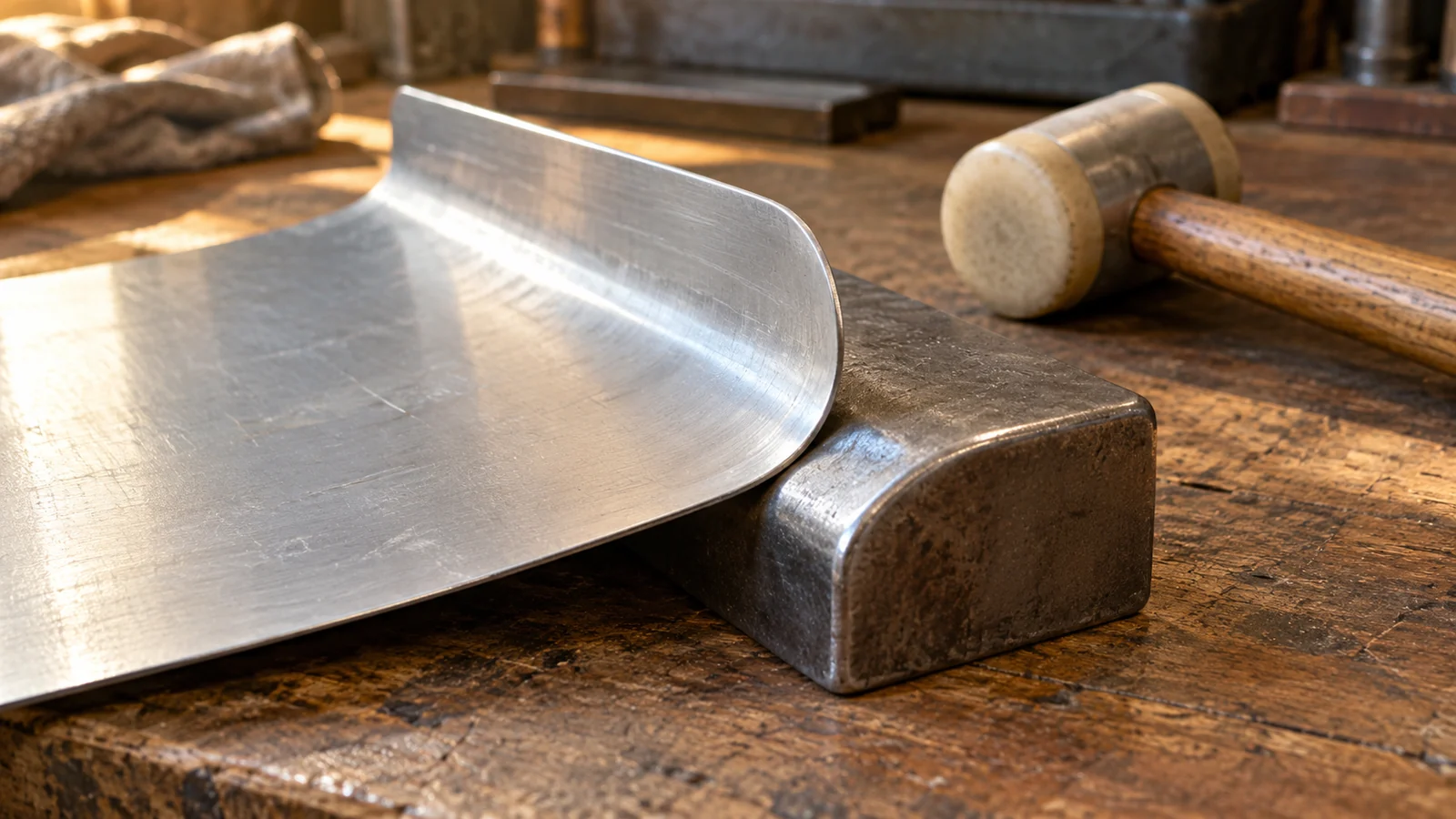
Equipment manufacturer Quintus describes fluid-cell forming in the context of aerospace prototyping and low-volume airframe production. That is a useful example of matching a process to a production mix, rather than treating conventional bending as the only sheet-forming option.
A low tooling price is not necessarily a low part cost. Include trial blanks, trimming, inspection, any permitted correction work and the risk of an unusable formed condition. A more controlled tool can be worthwhile when repeatable contour matters more than minimum initial expenditure.
Springback is a geometry problem, not just an angle
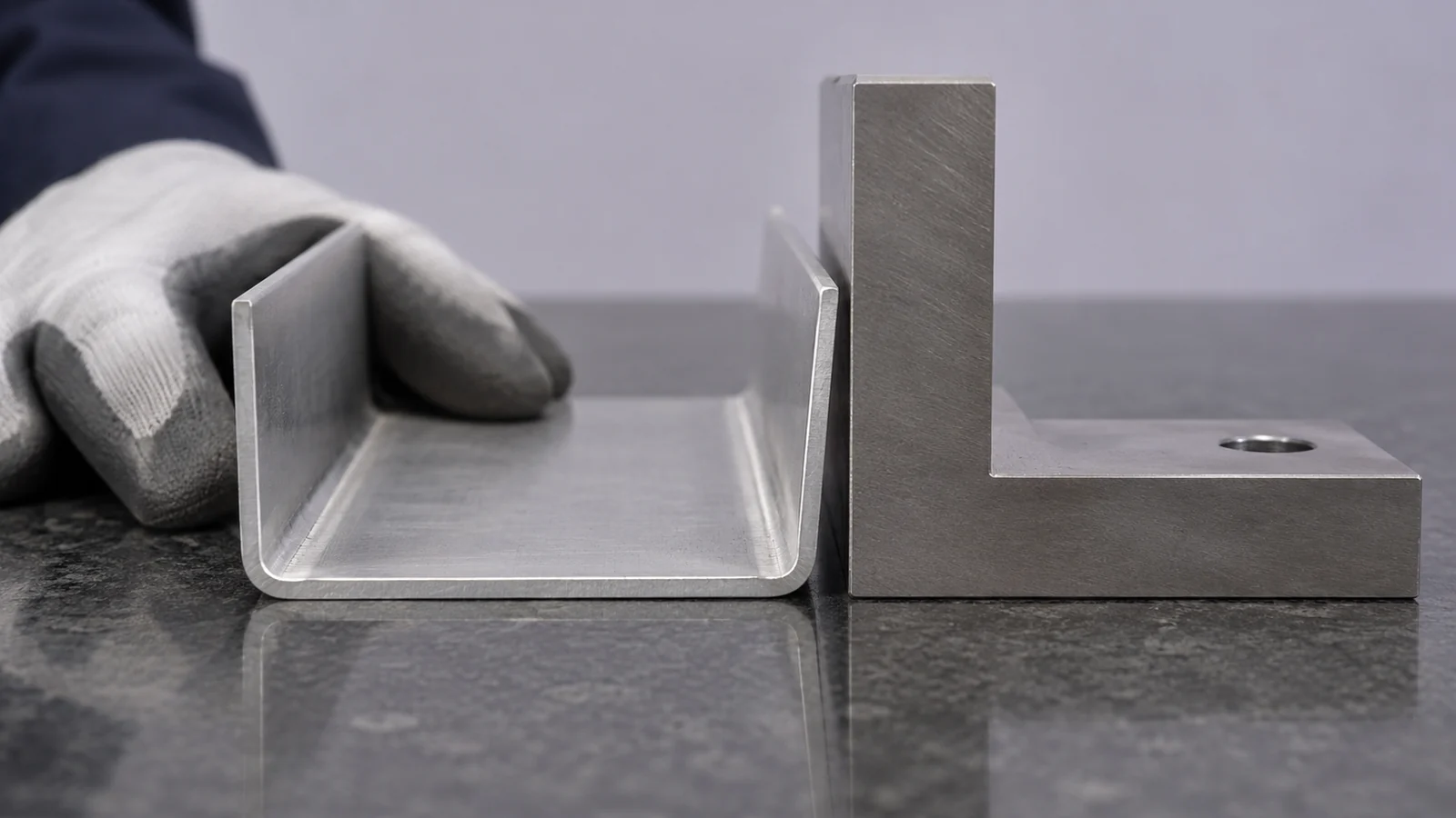
When the forming load is removed, the elastic portion of deformation recovers. On a simple bend, this may appear as an opening angle. On a channel or curved panel, the result may also include twist, changing radius or flange movement. Measuring one angle cannot describe all of these changes.
Compare the unloaded part with the specified datums and restraint condition. A channel that matches a checking tool only when forced into it may not satisfy a free-state requirement. Conversely, an assembly-restrained requirement needs the prescribed support, not an improvised free-state test. Establish that distinction before compensating the tool.
Research summarized by the Light Metal Educational Foundation examines springback prediction for aircraft sheet forming using simulation and experimental comparison. The practical lesson is to validate predictions against representative conditions; it does not provide a universal compensation angle for every alloy and shape.
Change one explanation at a time
Before increasing overbend, compare stock condition, actual thickness, lubrication, blank alignment and tool contact. If several variables changed between trials, the next result may not reveal which adjustment helped. Record both the setup and the measured released geometry. Where correction is allowed, define its limits and reinspection instead of leaving hand adjustment undocumented.
Holes, trims and finishes need a sequence
A flat blank is convenient to cut and drill, but convenience is not the only consideration. A hole close to a bend can distort as material flows. A hole used to locate a later operation may need to exist early. Final attachment holes may benefit from finishing after the major shape is established. Decide feature by feature rather than adopting an absolute rule that all holes come first or last.
Trimming has a similar dependency. Extra material may be needed for gripping or process development, while a final edge may need to be established after forming. The drawing’s edge distance and profile requirements apply to the finished condition. Retain enough access to inspect and deburr the resulting edge without damaging an adjacent flange.
Surface protection belongs in the route from the beginning. Tool contact, embedded debris and handling can leave damage that becomes obvious only after finishing. Confirm approved lubricants and cleaning methods, protect critical faces and define when coatings are applied. Do not assume a cosmetic finish can hide or repair an unacceptable forming defect.
When reviewing sheet metal fabrication services for a custom component, discuss the complete cut-form-trim-inspect sequence. An isolated bending quotation can miss the operations that determine whether the part will actually assemble.
Prove the route with a representative first part
Consider a hypothetical small channel with two flanges, attachment holes and a controlled mating surface. The first sample looks correct on the bench, but one flange moves when the part is released from its checking fixture. This is an illustrative troubleshooting case, not a customer project or a reported production result.
- Confirm the starting condition. Check the received stock against the planned alloy, temper, thickness and orientation.
- Separate forming from later distortion. Record geometry after forming and again after any required treatment, trimming or finishing.
- Inspect the functional interfaces. Evaluate flange relationship, hole positions and mating surface using the specified datums.
- Review integrity. Examine relevant bends and edges using the required acceptance methods; dimensional conformity alone does not establish freedom from defects.
- Freeze what worked. Identify the tool revision, operation sequence and accepted inspection setup before treating the route as repeatable.
A single successful sample does not demonstrate statistical capability. It provides an opportunity to find missing instructions and establish evidence for the next stage. Production acceptance, qualification and first-article obligations remain subject to the drawing, contract and applicable specifications.
Before releasing the next batch
The handover should state which material condition enters forming, which condition leaves the complete route and how the final shape is checked. Include approved tool information, blank orientation, process checkpoints and the disposition of any trial changes. This is more useful than telling the next operator to reproduce the sample by eye.
Can a larger bend radius solve cracking?
It may reduce local strain, but it is not an automatic remedy or an authorized design change. Investigate material condition, grain orientation, edge quality and tooling first. Any radius change must remain within the drawing or receive the appropriate approval.
Should the prototype use the intended production material?
Use representative stock when validating forming behavior. A softer substitute can be useful for checking access or basic geometry, but it cannot establish springback, damage resistance or final properties for the specified production condition. State exactly what a substitute prototype proves and what remains unverified.
Reliable aircraft sheet metal forming starts before the blank reaches the press. Getting the material condition and sequence right makes the later geometry checks meaningful, and gives the buyer a clearer basis for evaluating a formed part rather than just its appearance.

