


Ein Bauteil, das mit einer handelsüblichen Schieblehre 50,01 mm misst, aber nicht in seine Baugruppe passt, ist der ultimative Geist in der Werkstatt. In der traditionellen Welt der Längenbemaßung besessen wir von der "Größe" – dem Abstand zwischen zwei Punkten. Aber ein Bauteil kann die perfekte Größe haben und dennoch funktionell unbrauchbar sein, weil es verbogen, verdreht oder seine Merkmale falsch ausgerichtet sind. Dies ist die technische Krise, die durch Was ist GD&T (Geometrische Produktspezifikation und -tolerierung) gelöst wird. Es ist der Schritt von einer primitiven Längenmessung zu einer anspruchsvollen Funktionssprache. Es fragt nicht nur "Wie groß ist es?", sondern "Wo ist es und wie verhält es sich zum Rest der Baugruppe?" Im Bereich der hochwertigen CNC-Bearbeitungstoleranzen, ist GD&T die absolute Autorität.
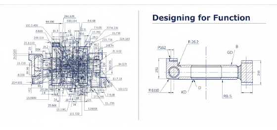
Bei Jucheng Precision haben wir Tausende von Projekten gesehen, bei denen ein Mangel an geometrischer Kontrolle zu teuren Montagefehlern führte. Wir verstehen, dass für ein Satellitengehäuse oder einen chirurgischen Roboterarm die Beziehung zwischen Merkmalen wichtiger ist als die Merkmale selbst. GD&T ermöglicht es Ingenieuren, genau zu kommunizieren, wie viel Abweichung akzeptabel ist, während sichergestellt wird, dass das Bauteil noch funktioniert. Dieser Leitfaden geht über die Lehrbuchdefinitionen hinaus, um die 14 geometrischen Symbole, die Anatomie des Merkmalstoleranzrahmens und zu erkunden, warum JUCHENG fortschrittliche CMM-Messtechnik einsetzt, um sicherzustellen, dass die "unsichtbaren" Toleranzen Ihrer CAD-Datei in der physischen Realität verankert sind.
Effizienz in der modernen Fertigung entsteht durch die Beseitigung von Mehrdeutigkeiten. Wenn Sie die Sprache von GD&T sprechen, eliminieren Sie den "Interpretationstanz", der oft zwischen dem Konstruktionsbüro und der Werkstatt stattfindet. Lassen Sie uns die technischen Säulen der geometrischen Kontrolle aufschlüsseln und sehen, wie sie die Integrität Ihrer komplexesten CNC-Konstruktionen neu definieren.
Das funktionale Gebot: Warum Größe nicht alles ist
Die 14 Symbole: Kartierung der Geometrie des Überlebens
Entschlüsselung des Merkmalstoleranzrahmens: Der Satz der Präzision
Die wirtschaftliche Realität: Prüfkosten vs. funktionaler ROI
JUCHENGs Messtechnik-Standard: Validierung des Unsichtbaren
Das funktionale Gebot: Warum Größe nicht alles ist

Um zu meistern Was ist GD&T, muss man zunächst das Versagen traditioneller +/- Toleranzen erkennen. Stellen Sie sich eine lange, schlanke Welle vor, die in eine präzisionsgeschliffene Bohrung passen soll. Ihre Zeichnung könnte einen Durchmesser von 20 mm +/- 0,01 mm vorgeben. Der Maschinist verwendet einen Mikrometer und bestätigt, dass die Welle an jedem Punkt exakt 20,00 mm beträgt. Nach linearen Maßstäben ist das Teil perfekt. Wenn diese Welle jedoch eine leichte "Bananenkrümmung" aufweist – einen Geradheitsfehler – wird sie niemals in die Bohrung gleiten. Die lineare Bemaßung hat die Form nicht berücksichtigt.
GD&T verschiebt die Zielsetzung von 1D-Zahlen zu 3D-"Toleranzzonen". Anstatt nur einen Abstand zu definieren, definiert es ein zylindrisches oder planares Volumen, in dem das gesamte Merkmal vorhanden sein muss. Es erlaubt einem Ingenieur zu sagen: "Mir ist wichtig, dass diese Welle 20 mm ist, aber mir ist *wichtiger*, dass sie innerhalb von 0,005 mm gerade ist." Dieser funktionale Fokus ermöglicht "Bonustoleranz" – ein kritisches Konzept im CNC-Bearbeitungsprozess. Wenn eine Bohrung etwas größer als ihre Mindestgröße bearbeitet wird, kann GD&T (unter Verwendung von Modifikatoren wie MMC) dem Maschinisten tatsächlich mehr Spielraum für die Position der Bohrung geben. Dies reduziert Ausschussraten, ohne die Passfähigkeit der Baugruppe zu beeinträchtigen. Bei Jucheng Precision nutzen wir diese funktionale Logik, um unsere Werkzeugwege zu optimieren und sicherzustellen, dass wir die Spezifikationen treffen, die für Ihr Endergebnis wichtig sind, nicht nur die Zahlen auf dem Papier.
Die 14 Symbole: Kartierung der Geometrie des Überlebens
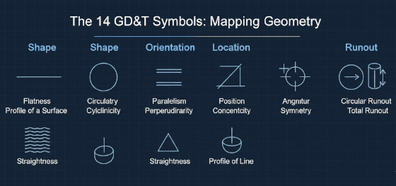
Die Leistungsfähigkeit von GD&T wird in 14 eindeutigen Symbolen zusammengefasst, die durch die Normen ASME Y14.5 oder ISO 1101 geregelt sind. Diese Symbole sind der Fahrplan für CNC-Bearbeitungstoleranzen. Wir kategorisieren sie in vier Hauptfamilien basierend auf dem, was sie steuern. Das Verständnis, welches Symbol zu verwenden ist, macht den Unterschied zwischen einem Hochleistungsteil und einem fertigungstechnischen Albtraum aus.
1. Formtoleranzen: Diese definieren die Form eines einzelnen Merkmals. Ebenheit, Geradheit, Rundheit, und Zylindrizität Stellen Sie sicher, dass eine Oberfläche nicht wellig oder eiförmig ist. Diese benötigen kein "Datum" (Bezugspunkt).
2. Orientierungstoleranzen: Diese beziehen ein Merkmal auf ein Datum. Rechtwinkligkeit, Parallelität, und Winkligkeit Stellen Sie sicher, dass eine Bohrung perfekt "rechtwinklig" zu einer Montagefläche ist.
3. Lagetoleranzen: Dies ist das Herzstück von GD&T. Position (Wahre Position) ist das aussagekräftigste Symbol, das genau definiert, wo sich ein Loch oder ein Vorsprung im 3D-Raum befindet. Konzentrizität und Symmetrie sind die selteneren, teureren Verwandten der Position.
4. Lauftoleranzen: Diese sind für rotierende Teile unerlässlich. Rundlauf und Gesamtlauf messen, wie stark ein Merkmal "wackelt", wenn es sich um eine Achse dreht. Bei Jucheng Precision sind wir auf hochdrehende Rotationsteile spezialisiert, bei denen der Gesamtlauf innerhalb von einstelligen Mikrometern gehalten werden muss, um Lagerausfälle bei 10.000 U/min zu verhindern.
Entschlüsselung des Merkmalstoleranzrahmens: Der Satz der Präzision
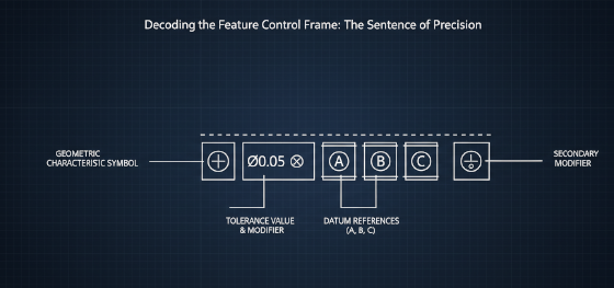
Wenn die Symbole das Vokabular von Was ist GD&T, dann ist der Feature Control Frame (FCF) der Satz. Es ist ein rechteckiger Kasten, der alle technischen Anweisungen enthält, die zur Bearbeitung eines bestimmten Merkmals erforderlich sind. Ein FCF wird von links nach rechts gelesen und bietet eine logische Abfolge der geometrischen Absicht. Für Uneingeweihte sieht es wie ein verschlüsselter Code aus; für einen JUCHENG-Maschinisten ist es ein chirurgischer Befehl.
Das erste Fach enthält das geometrische Symbol (z. B. Position). Das zweite Fach definiert Form und Größe der Toleranzzone (z. B. einen Durchmesser von 0,05 mm). Darauf folgt oft ein Materialmodifikator wie MMC (Maximum Material Condition), which is the engineer’s secret weapon for cost reduction. MMC essentially says: "If the hole is at its smallest (hardest to fit), the position must be perfect. But if the hole is larger, you get extra 'bonus' tolerance for its location." The final compartments define the "Datums"—the A, B, and C faces that the part will be measured from. At Jucheng Precision, we use our 5-axis machines to establish these datums in a single setup, ensuring that the entire "Datum Reference Frame" is perfectly synchronized with the machine's coordinate system. This eliminates the manual error associated with trying to find a zero-point across multiple fixtures.
Die wirtschaftliche Realität: Prüfkosten vs. funktionaler ROI

Sprechen wir über die Rechnung. Es gibt einen hartnäckigen Mythos, dass GD&T Teile immer teurer macht. Dies ist ein Missverständnis der Fertigungsökonomie. Es stimmt zwar, dass eine Was ist GD&T callout requires more advanced inspection—you cannot verify "True Position" with a ruler—it actually lowers the *total cost of quality*. Traditional linear tolerances are often too tight because the engineer is trying to "guarantee" a fit they can't accurately describe. This leads to parts being scrapped that would have actually assembled perfectly.
GD&T provides the "functional wiggle room" that manufacturing needs. By using MMC and defining tolerance zones instead of rigid lines, you give JUCHENG the ability to hit the functional requirements without having to maintain impossible linear precision on non-critical features. The investment shifts from the machine floor (where high scrap rates are expensive) to the QC room (where precision validation is a known, fixed cost). For high-volume production in the automotive and medical industries, GD&T is a massive budget protector. It ensures that the assembly line never stops because of a part that "measures right but fits wrong." We help our clients perform this ROI analysis during the DFM phase, showing you where a single Position callout can replace ten linear dimensions and save you 20% on your unit price.
JUCHENGs Messtechnik-Standard: Validierung des Unsichtbaren
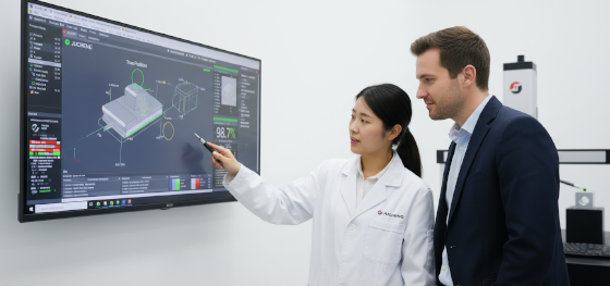
The final hallmark of a 5-axis facility is the ability to prove the geometry. CNC-Bearbeitungstoleranzen are only as good as the metrology that validates them. You cannot "see" a parallelism error of 0.02mm, but you will certainly feel the heat it generates in a high-speed assembly. Jucheng Precision has invested in the ultimate GD&T validation tool: the Coordinate Measuring Machine (CMM).
Our CMMs are not just checking sizes; they are checking relationships. We use specialized software to interpret your GD&T callouts and generate a graphical "True Position" report. We can show you exactly where the center of a hole is relative to its theoretical master coordinate. This transparency is essential for aerospace and defense contracts where every micron of geometric deviation must be documented. When you receive a component from JUCHENG, you aren't just getting metal; you are getting a verified engineering solution. We bridge the gap between a complex series of symbols on a blueprint and a functional physical part that assembles perfectly every time. Whether you are building an innovative medical device or a high-performance EV drivetrain, our GD&T expertise clarifies your design vision and protects your reputation. Contact Jucheng Precision today for a technical review of your next precision project.

