


An aircraft flap track roller may look like a small wheel, yet its geometry helps maintain a moving interface within a larger high-load assembly. The roller’s groove or running profile, bore, shoulders, retention features, and relationship to its support all matter. Manufacturing review should begin by identifying how the roller contacts the track and how the assembly constrains it, rather than treating the part as a generic turned cylinder. The term aircraft flap track roller manufacturing describes this drawing-led part and process scope; it does not replace the program’s approved design requirements.
This article is a manufacturing-planning guide for drawing-defined roller components and development parts. It does not establish aircraft design limits, fatigue life, or airworthiness. Those remain with the approved design and quality system. The discussion focuses on datum relationships, material and process definition, machining sequence, inspection, and information buyers should provide when requesting a quotation.
Contents
- Understand the roller-to-track contact
- Establish the bore and running profile relationship
- Plan stock and machining sequence
- Define surface condition without guessing performance
- Keep shoulders, spacers, and retention features coordinated
- Inspect the features that govern assembly
- What a roller RFQ should contain
- Frequently asked questions
Understand the roller-to-track contact
Start with the assembly drawing or interface model. Identify the track surface, roller support, bearing or bushing arrangement, retention stack, and the range of motion described by the design. The roller profile may be crowned, grooved, flanged, or otherwise shaped, but the drawing must define the intended form. A supplier should not infer the profile from a rendered assembly, particularly if the contact region is partially hidden.
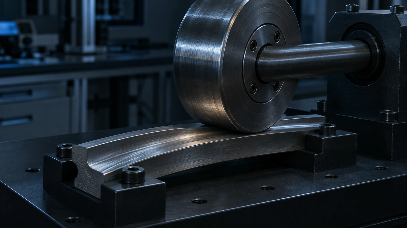
Clarify whether the roller rotates directly on a shaft, contains a bearing, or uses a separate sleeve. That changes which diameter, surface, and retention face are functionally important. Define the direction of the applied load and the contact area only to the extent needed for manufacturing interpretation; the design authority retains responsibility for load limits and life calculations. If the drawing contains a profile or finish callout without a measurement reference, resolve it before the first article so the inspection plan evaluates the intended feature.
Establish the bore and running profile relationship
The bore axis and running surface generally need a controlled relationship. Depending on the design, the relevant checks may include profile, runout, concentricity-style position controls, or a specified geometric tolerance. Use the drawing’s chosen datum reference and do not substitute a different control simply because it is easier to measure. If the roller is turned and then moved to another setup for the bore or groove, setup transfer can influence the relationship between those features. Aircraft flap track roller manufacturing should relate the running profile and bore to the same drawing datums used to define assembly position.
For a part with multiple shoulders, define which face sets axial location and which features provide clearance. A datum scheme based on the way the roller is assembled makes it easier to decide how to hold and inspect it. The manufacturing team can propose a fixture or sequence, but engineering must approve any changed tolerance or inspection interpretation. When a model-based definition is used, ensure the controlled model, revision, and annotations are available to both the shop and the inspector.
Plan stock and machining sequence
Choose the blank material and condition from the approved specification. The supplier needs to know whether the roller is made from bar, a near-net blank, or another defined stock form, and whether heat treatment or another process occurs before or after machining. Each route affects stock allowance and final feature sequence. A prototype made from bar may support interface evaluation but may not represent every characteristic of a production blank.
For turned geometry, roughing and finishing operations should leave enough control to achieve the drawing-defined profile and bore relationship. If heat treatment or coating follows machining, plan which surfaces are protected, which dimensions are checked before treatment, and which are verified afterward. Avoid assuming a standard allowance or sequence without the material and process specification. The site’s CNC machining capability is relevant to a drawing-based component discussion; the customer’s design and approved route determine the actual requirements.
Define surface condition without guessing performance
Contact and bearing surfaces may have specified roughness, hardness, coating, or other requirements. These values must be provided by the design authority and tied to a measurement method where necessary. A generic “smooth finish” note is difficult to quote and verify. If a coating is called out, specify its type, thickness or applicable range, masking zones, and the evidence required. A supplier should not infer the roller’s service class from the aircraft context and invent a surface requirement.
Edge treatment also matters around the bore, shoulders, and groove transitions. Burrs can interfere with assembly or damage a mating surface, while excessive edge breaking can alter a designed contact profile. Identify edges that need a controlled break and edges that must remain defined. If finishing happens after heat treatment, consider how the route may affect dimensions and surface integrity, and ask for only the records stated in the purchase specification. No visual inspection alone should be represented as proof of fatigue life or operational suitability.
Keep shoulders, spacers, and retention features coordinated
Rollers rarely function as isolated parts. Their width, shoulder position, spacer stack, fastener, and support bracket can determine lateral movement and axial location. The assembly drawing should make clear which part controls each relationship. If a spacer is supplied separately, note its thickness and contact faces. If the roller includes an integral shoulder, its relation to the running profile and bore must be specified and inspectable.
Before releasing a prototype, check that the physical assembly can be built without forcing the roller into a constrained position. This is a fit check, not a substitute for structural or system validation. Document which neighboring parts and revisions were used. If changes to a bracket, track, or shaft are still pending, mark that condition in the sample plan. This prevents a prototype fit result from being interpreted as an approval of the final aircraft assembly.
Inspect the features that govern assembly
A first-article plan can include bore size and form, overall width, shoulder location, running profile, and the defined relationship between the axis and contact surface. Select measurement techniques that can access the actual geometry. A profilometer, optical system, roundness instrument, or coordinate measurement may be suitable depending on the specified characteristic; the drawing and quality plan should determine the method, not a broad assumption that one instrument can prove everything.
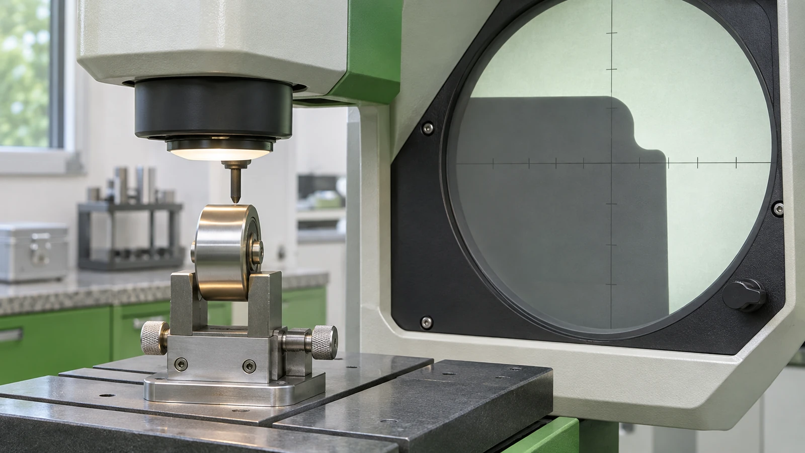
Record part identity, drawing revision, material and condition, process status, measurement units, and any post-process condition. If the roller is checked before and after coating or heat treatment, clearly label which result corresponds to each stage. If sampling is required, use the customer-defined plan. The report should separate dimensional results from any functional test. Where a functional fixture is requested, define its datums, mating parts, and acceptance criteria in advance so the check is repeatable and does not imply an unstated certification.
What a roller RFQ should contain
Provide the roller drawing and model, associated assembly interface, material and condition, expected quantity by release, prototype or production stage, heat-treatment or coating requirements, and inspection records. Mark the running profile, bore, axial location faces, and any controlled edge condition. Include the track or mating geometry needed to interpret the interfaces while keeping ownership of the aircraft system requirements clear. An aircraft flap track roller manufacturing RFQ should state the specified material condition, retention stack, surface requirements, and reportable characteristics.
Ask suppliers to identify open questions about datum transfer, machining stock, finish verification, and sequence around post-processing. A complete quote should make clear whether material, outside processes, inspection, and sample documentation are included. If the design is still evolving, identify the current revision and the features likely to change. A disciplined package supports a meaningful supplier review without claiming that a manufacturing quote validates the aircraft system.
For broader component-route context, see aerospace manufacturing processes; the approved drawing and quality plan define the requirements for this roller.
Frequently asked questions
Is the roller’s outside diameter the only critical dimension?
Usually not. The bore, running profile, width, shoulder location, and their relationships may all affect assembly. Use the controlled drawing to identify the required characteristics.
Can a machined sample establish fatigue life?
No. Dimensional samples can support manufacturing and fit evaluation, while fatigue or service-life evidence requires an approved test plan and responsible design authority.
Should the supplier select the roller coating?
The supplier can explain process options, but the design specification and approval process must define the accepted coating and evidence.

